Generator Fuel System Design in the UAE: Sizing, Architecture and Civil Defence Compliance
Designing a UAE generator fuel system comes down to a short list of decisions — how much fuel, in what arrangement, delivered how, contained how, approved by whom — with four principal arrangements to choose between. This guide takes them in order, before it is built.

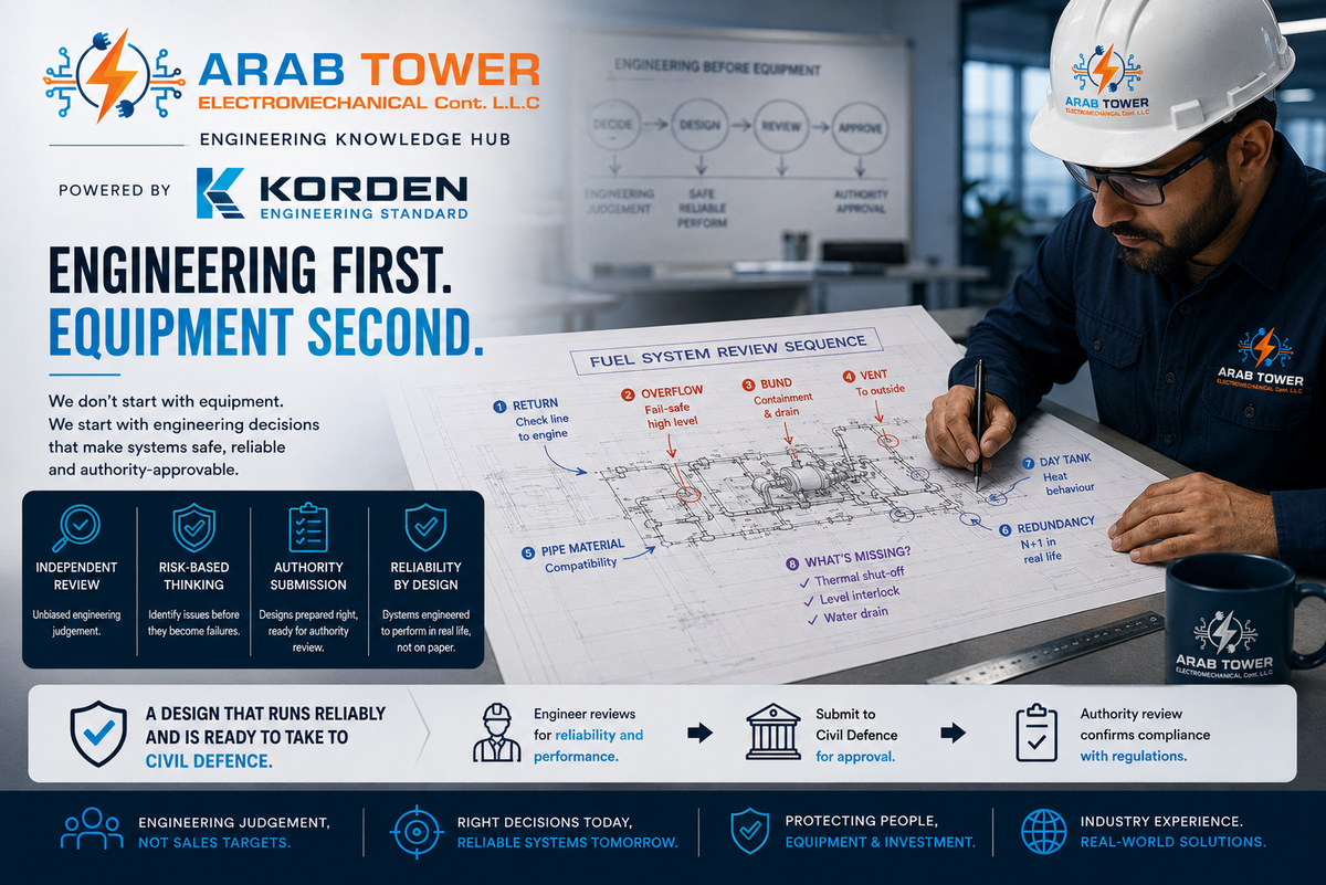
Designing a generator fuel system comes down to a short list of decisions: how much fuel to store, in what arrangement, how to deliver it to the engine, how to contain it, and what Civil Defence needs to approve. Get them right on paper and most of the risk is removed before site. This guide takes them in order, starting with how much fuel the site needs — the autonomy figure that drives the arrangement and everything after it.
Four principal arrangements:
- Sub-base (belly) tank — a tank under the set. For short, limited autonomy and non-critical duty; the engine feeds directly, with no separate day tank. Simplest and cheapest.
- External bulk + day tank — bulk stored outside (bunded or underground) with a day tank at the engine, fed by a transfer pump. For longer autonomy where there is outside space; outdoors, separation and open air do much of the fire protection for you.
- Indoor bulk + day tank (fire-rated room) — bulk inside a fire-rated tank room when outside storage is not possible. Adds the full Civil Defence compliance layer — the protection that distance would otherwise give for free.
- Shared bulk + independent day tanks — one bulk tank feeding several sets, each with its own day tank and duplex transfer pumps. For multiple generators.
They differ by three things: how much autonomy you need, where the bulk can live (outside vs a fire-rated room), and how many sets you feed. Settle the arrangement first — it tells you which sections below apply. Every project needs the sizing, delivery, heat-management and drawing-review sections; indoor storage adds the containment and compliance sections; multiple sets add the shared-bulk redundancy.
After reading this, you will be able to
- size the fuel store — from autonomy to a defensible tank capacity;
- choose the right architecture using the three gates;
- design the delivery, containment and compliance layer Civil Defence looks for;
- review any fuel-system drawing in under a minute before it goes to the authority.
The UAE Fire & Life Safety Code is a controlled document — its clause values are confirmed against the licensed Code and the local Civil Defence office, and can differ by emirate. So every requirement below is named and explained, and every number is either sourced (source named) or flagged to confirm with the authority; distances from international codes are not carried over as UAE values. Fuel approval is a Civil Defence matter; the electricity companies — DEWA, SEWA, Etihad Water & Electricity, ADDC — are the electrical interface only and do not approve the fuel tank.
One example runs through the guide: a mid-rise commercial block, standby power required. Its inputs are assumptions to show the method, not a certified design — an ≈800 kVA / 640 kW set, autonomy assumed at 24 h, bulk fuel in the basement with the set and day tank on the roof (~30 m above). Substitute your set's certified OEM data and your project's confirmed values.
How much fuel — autonomy, then a defensible tank size
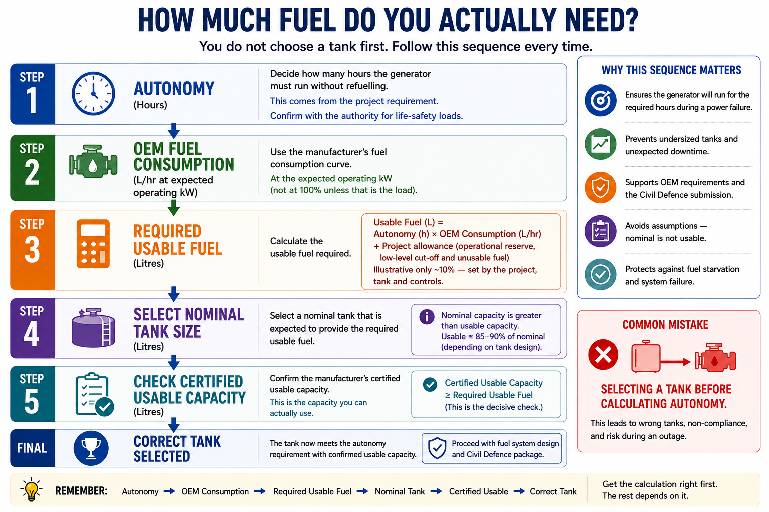
Every fuel system starts with one number: how many hours the set must run at load before someone refuels it — its autonomy. That number sets the litres, and the litres set the tank, the architecture and much of what follows.
The decision — set the autonomy (hours at load before a refuel), convert it to usable fuel, then choose a tank whose certified usable capacity meets it.
Autonomy is a decision, not a lookup: driven by how critical the load is and how reliably a tanker can reach the site. Emergency-power practice frames stored fuel as a duration class set by the occupancy and the authority (the reference is NFPA 110) — so confirm the required duration for your occupancy rather than copying it.
(the article's principal calculation; inputs stated as assumptions)
① Consumption comes from the selected genset's certified consumption curve at the expected real kW load — not from kVA, and without an "ambient uplift" (ambient reduces the available rating, a derating handled in set sizing; it does not inflate litres-per-kW). Illustrative OEM figure: ≈ 130 L/h.
② Autonomy → usable litres. 130 L/h × 24 h = 3,120 L, plus the operational reserve, low-level cut-off and unusable heel (set by the tank geometry, controls and any code margin — an illustrative allowance here) ≈ 3,430 L usable.
③ Usable → tank. Certified usable volume is less than nominal (fill ullage, heel, cut-off — often ~85–90 % of nominal), so nominal ≥ 3,430 ÷ ~0.88 ≈ 3,900 L.
→ Select a ≈4,000 L-class tank, and confirm its certified usable capacity ≥ 3,430 L. The arithmetic proves the selection only against usable capacity.
Whether day-tank contents may be credited toward this store depends on the governing code and the authority's usable-volume definition — generally not.
Which architecture — and how the choice is made
You met the four arrangements at the top. Here is how you actually land on the right one for your project — three gates, taken in order.
The decision — the shape of the system: a sub-base tank under the set, or a day tank fed from bulk (with the bulk outside, in a fire-rated room, or shared across several sets). Three gates settle most projects.
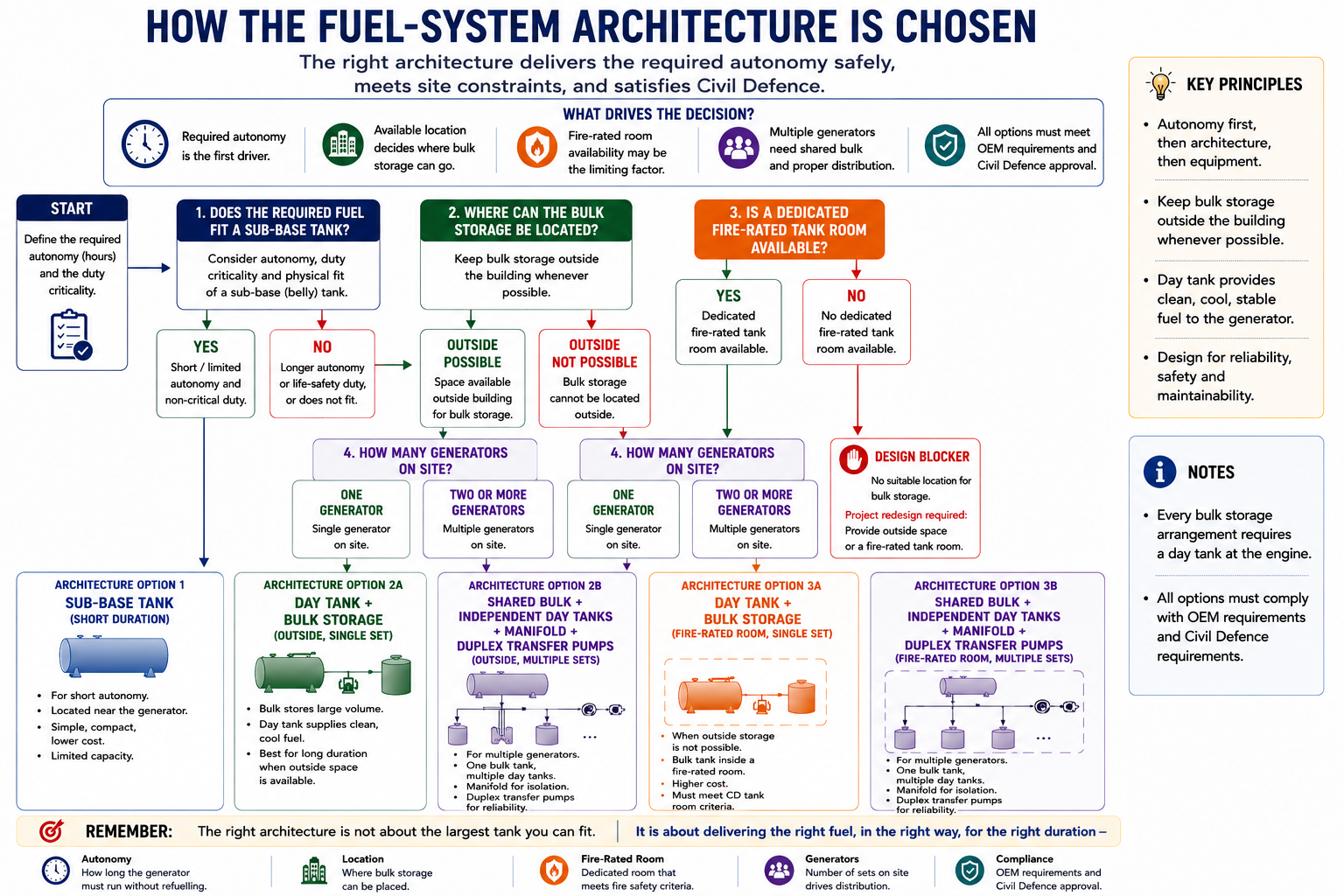
Gate 1 — How much autonomy? (Confirm the duration with the authority.)
- A few hours, non-critical → a sub-base (belly) tank may be enough — the arrangement is settled (Option 1); no further gate. (Indoor siting still adds the containment and compliance sections.)
- Longer, life-safety/critical, refuel not assured → day tank + bulk storage → Gate 2.
Gate 2 — Where can the bulk fuel live?
- Outside, with space → an external bunded tank or underground tank, day tank at the engine fed by a transfer set.
- Only inside/under the building → a fire-rated tank room; the full compliance layer applies.
- Feeding more than one set → one bulk tank on a manifold, isolation per branch, an independent day tank per set, duplex transfer pumps on independent power.
Gate 3 — Inside/under the building, or outside?
- Outdoors, clear of openings → separation, containment, safe vent/fill termination.
- Indoors or in a plant room → the full compliance layer and the UAE heat/aeration checks on the day tank.
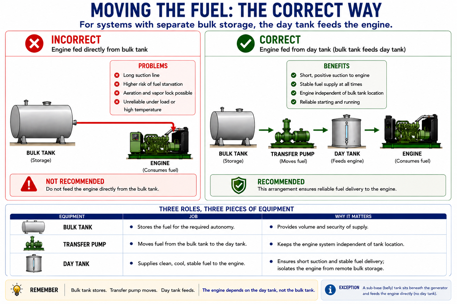
The day tank exists because when the bulk store is far from the engine — a basement tank feeding a rooftop set, or a shared bulk feeding several sets — the engine cannot draw fuel reliably over that distance and lift. It sits near the engine, holds a short run's worth, and is topped up from bulk by a transfer pump.
(an indicative range to verify, not a full calculation)
There is no single formula here: the day tank is selected, then checked. OEM guidance commonly starts at roughly two hours at full load; confirm the size against the OEM connections and flow, the usable volume between pump start and stop, the pump's cycle limits, and the return's residence time.
→ Commonly a listed tank in the ~500–1,000 L class for a set this size — a procurement range to confirm against the OEM and the control design.
Moving the fuel — delivery and genuine redundancy
Storing the fuel is only half of it; the fuel then has to reach the engine clean, and keep reaching it if a pump or line fails. That is what this section designs.
The decision — deliver the fuel clean, and make the delivery path genuinely redundant, not the alternators alone.
Draw both the supply and the return line — a missing or mis-routed return is a common source of fuel problems. Use flexible connectors at the engine for vibration. Where the bulk store is beyond the engine's own suction, a transfer pump set refills the day tank on level control.
The zinc can react with diesel and shed particulate that fouls filters and injectors. Use black steel, or another spec-compatible material — confirm against the project spec and the OEM's requirements.
(a detailed-design layer for designers and contractors, not a first-pass calculation)
Locate the pumps at low level beside the bulk tank — flooded suction, the ~30 m lift on the discharge side. Set the flow so the day tank refills across its control band without short-cycling; head = static lift + pipe friction + fitting and valve losses + filter drop; verify on the pump curve with NPSH margin.
→ Duplex pumps on independent power; flow, head and NPSH computed in detailed design.
Two "N+1" generators behind one shared fuel line and one transfer pump are N+1 at the alternator and N in the fuel — trace the fuel path physically. Real redundancy means independent day tanks, duplex pumps on independent power, and branch isolation off a shared manifold.
How the fuel behaves — heat and the return
A diesel engine sends most of the fuel it draws back to the day tank, warm — and in a hot UAE plant room that returned heat is the problem this section solves. Manage it wrong and the set derates under sustained load; manage it right and the tank quietly sheds the heat.
The decision — manage the warm engine return so its heat is rejected before the fuel is drawn again: separate the return from the suction, size and locate the tank to shed heat, and add a fuel cooler where the OEM requires it.
A large fraction — often most — of the fuel an engine draws may be returned warm to the day tank, depending on the engine's fuel system. In a hot UAE plant room the returned heat can push the fuel toward or past the OEM's permitted fuel-inlet-temperature limit, causing performance problems or derating under sustained load. Air in the fuel makes an engine hunt and run rough — a fault a load-bank run typically exposes and a five-minute test usually does not; the usual air paths are leaks on the suction side and an air-lock from a trap in the return line, so suction-side joints must be airtight and the return must fall continuously to the tank without traps.
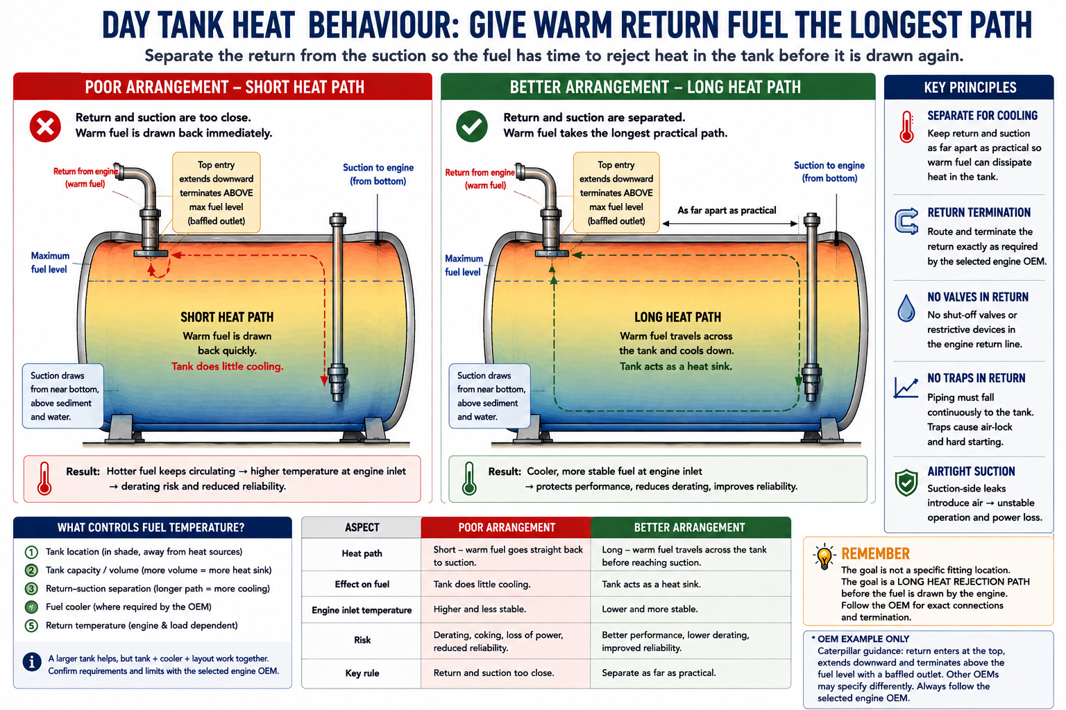
Route the return exactly as the selected engine OEM requires — do not assume a submerged termination is universally correct. Caterpillar's guidance, for example, uses a top-entry return that extends downward and terminates above the fuel level, with a baffled outlet, and carries no shut-off valve or harmful restriction in the engine return (a closed valve builds damaging pressure). Separate the return and the suction as far apart as practical, so the warm returned fuel has the longest available path to dissipate heat before it is drawn again. Temperature is controlled by the tank's volume and location, and — where the OEM requires it — a fuel cooler when the tank alone cannot reject enough heat; a larger, well-proportioned tank helps by adding thermal mass. The exact limits, return routing and cooler requirement come from the selected OEM's data.
Containing it — the bund and the fire-rated room
From here the design assumes the primary system will one day leak, overflow or be exposed to fire, and makes that survivable. This is the layer the authority cares about most — and, for indoor storage, the one that adds the most engineering.
The decision — catch the fuel when the system fails: secondary containment to the confirmed margin, and a fire-rated room wherever the fuel is indoors.
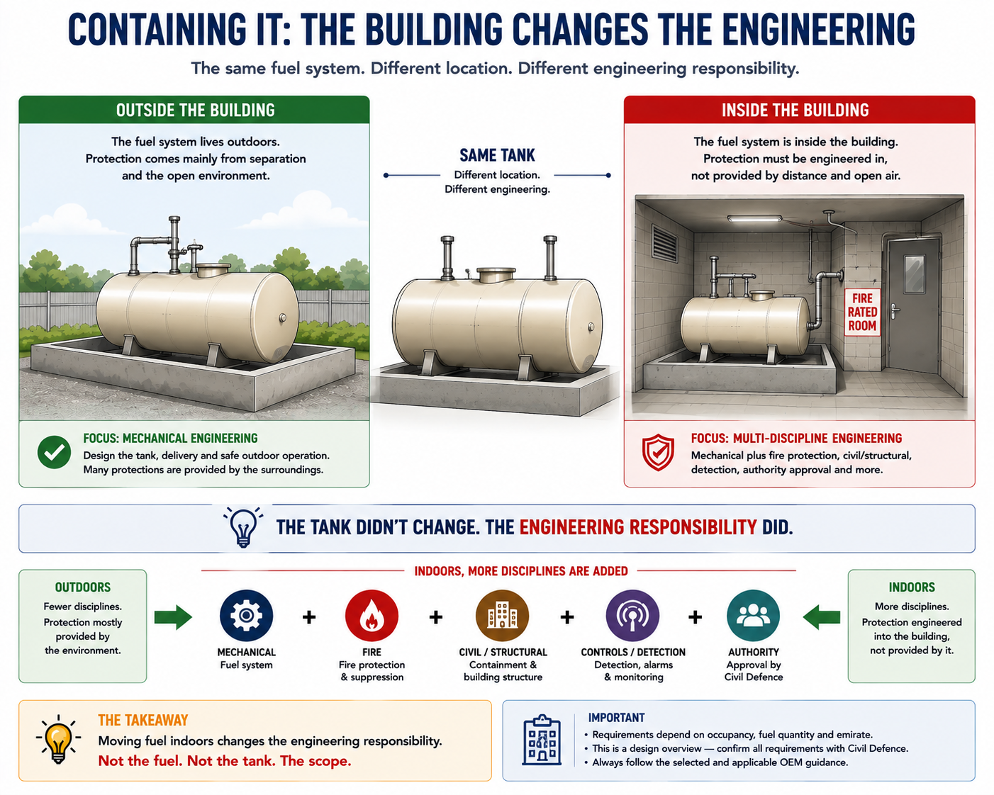
Secondary containment catches escaping fuel before it reaches the building, drains or ground — an integral double-wall on a listed tank (UL-142/2085), or a bund around an external tank. The UAE's published fuel-storage regulation sets the margin at at least 110 % of the largest tank (Abu Dhabi DoE Fuel Storage Tanks Regulations 2023, §3.5.2). That regulation governs utility-scale tanks, not building gensets — so treat 110 % as the regulator's articulation of the principle, a sound target to bring to Civil Defence and confirm, not an automatic building mandate. Keep the bund impermeable and diesel-compatible, with a normally-closed rainwater drain and no general storage inside it.
Indoor storage is typically placed in a fire-rated enclosure with a self-closing fire-rated door and sealed penetrations — but the required enclosure, rating and separation depend on the occupancy, the stored quantity, the equipment arrangement, the licensed UAE Code and the AHJ. Higher-hazard rooms are commonly two-hour construction and that is what experienced UAE engineers design to; confirm the rating and door specification with Civil Defence. (Room compartmentation → Generator Room Design guide.)
A standby tank sits mostly idle and breathes humid UAE air, condensing water at the bottom — so give the water somewhere to collect and be removed (a sloped bottom, sump or draw-off point, and a breather/desiccant where warranted). The servicing and polishing regime itself is the fuel-maintenance guide's.
Making it compliant — vent, fill and overflow
These are the small details Civil Defence checks first, because they fail worst: how the tank breathes, where it is filled, and what happens when it is overfilled or a fire reaches the engine.
The decision — let the tank breathe, terminate vent and fill outside, and make the overflow fail-safe by gravity where the layout allows.
Venting is a selection sized by the governing method for the tank type, not a number quoted here: for a bulk atmospheric tank, the petroleum-tank venting standard (API 2000); for listed sub-base or day tanks, the manufacturer's instructions and the governing fire code may control instead. Size normal breathing to pass air at least as fast as the maximum fill or empty rate, and emergency relief for the fire-exposure case; keep both clear and unblocked.
Termination and separation are two different requirements. The normal vent and the fill line terminate outside, clear of doors, windows, air intakes and ignition sources. Tank/engine separation from openings and combustible construction is a separate matter. Both distances are set by Civil Defence — confirm them; do not carry over figures from international codes.
The overflow should not need power. A gravity overflow back to the bulk tank is the preferred fail-safe where the layout permits and the standard/authority accepts it, because it works with no pump and no power — where a pumped overflow would fail on power loss, exactly when the set is running and the day tank is filling. Add fail-safe automatic high-level shut-off (functioning on power loss), an independent high-level alarm, and level indication interlocked to the fill valve and transfer pump; interstitial monitoring on double-wall tanks and piping (Abu Dhabi DoE 2023, §3.7 overfill, §3.4 leak detection).
Thermal shut-off. A thermally actuated (fusible-link) shut-off on the engine fuel line closes on heat and isolates the fuel on a fire — standard fire-safety practice; provide it and confirm the requirement with the authority.
Reviewing it before the Civil Defence submission
Everything above meets here: before the drawing goes to the authority, an experienced reviewer runs it in a set order that catches both the reliability faults and the compliance gaps. This is the sequence.
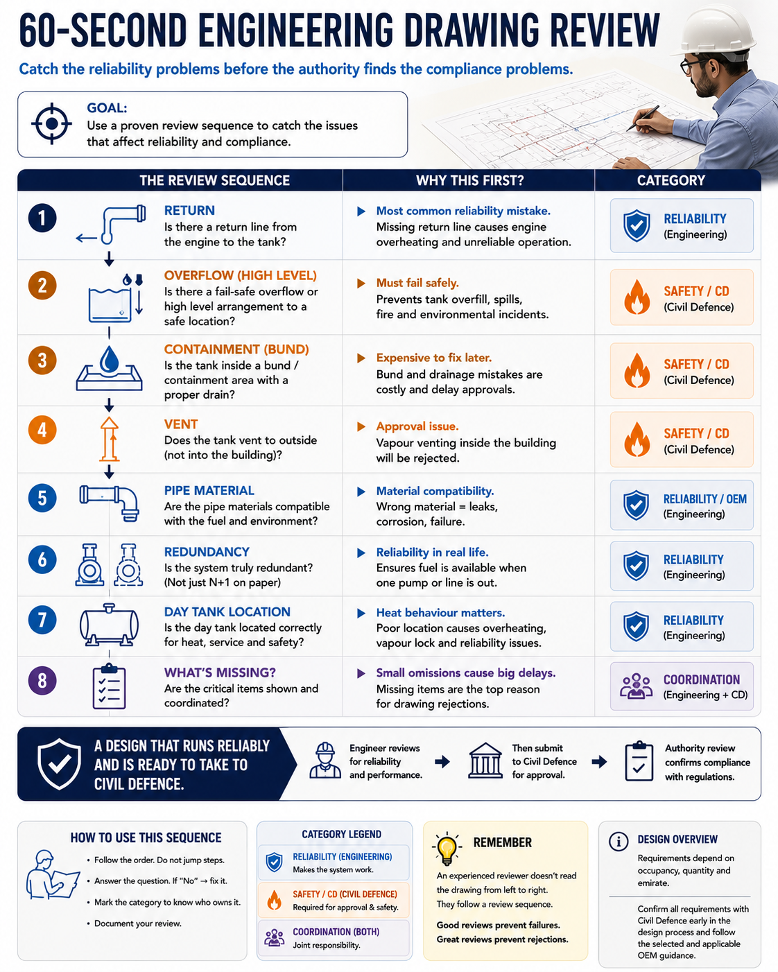
Do not start at the tank size — start where designs fail, in this order:
- Return — drawn, to the right tank, routed per the engine OEM and separated from the suction?
- Overflow — gravity to bulk, or pumped (a pumped overflow should trigger scrutiny — is it independently powered and fail-safe)?
- Bund and its volume, and where the vent terminates — outside, or quietly indoors?
- Pipe material — spec-compatible (black steel), or silent/galvanised?
- Redundancy on multi-set jobs, and the day-tank location against its plant room and the OEM inlet-temperature limit.
- What is missing — thermal shut-off, water drain, level interlock. A drawing tells you as much by omission as by content.
Build in the order that protects the programme — compliance-critical items first, because a bund, room rating or vent termination found wrong after the pipework goes in is rework, not a correction. The hold-points that must be signed before proceeding: containment complete and tested; tanks and pipework set, pressure-tested and proven clean before they are covered; vent/fill terminations confirmed outside with the authority; penetrations fire-stopped; alarms and interlocks functionally tested; then the Civil Defence inspection against the approved drawings (the exact approval sequence depends on the project and emirate). Commissioning under real load then confirms it — see the Commissioning and Load-Bank guide.
Review in order: return → overflow → bund → vent → pipe material → redundancy → day-tank location → what's missing. Under a minute, it tells you whether a fuel system was designed to reach the engine and pass the authority.
Standards, references and how Arab Tower can help
Governing authority. A UAE building's generator fuel system is approved by Civil Defence under the UAE Fire & Life Safety Code of Practice — the authority on fire rating, thermal shut-off, vent and fill termination, indoor storage limits, separation and suppression. Clause values and distances are confirmed against the licensed Code and the local Civil Defence office per project, and practice can differ by emirate.
Supporting references. The Abu Dhabi DoE Fuel Storage Tanks Regulations 2023 is the published UAE source for the 110 % containment principle, fail-safe overfill and leak detection (utility-scale scope, cited as the regulator's articulation of the principle). NFPA 110 frames fuel storage as a required duration and the day-tank-and-transfer arrangement; NFPA 37 and the IFC are the international basis for engine/tank separation and venting; NFPA 30 / 31 for containment; UL 142 / 2085 for tank construction; API 2000 for atmospheric-tank vent sizing; ISO 8528 for the fuel-consumption basis. These are supporting references; the mandatory requirement in the UAE is what Civil Defence approves, and international distances are not carried over as UAE values.
How Arab Tower can help. Arab Tower designs, supplies, installs, tests and commissions generator fuel systems in the UAE and internationally, and reviews them independently before they are built. The most useful next step is an independent review of the fuel-system design and its Civil Defence compliance before it goes to the authority — send the generator location, the required autonomy and the loads that set it, and the layout or single-line you have. The review stands on its own whether or not the equipment is bought from us.
Talk to our engineers → · or explore our generator range.
Go deeper: Generator Sizing · Generator Room Design · Generator Earthing & Protection.