Generator Earthing & Protection: How to Earth and Protect a Standby Generator in a UAE Building
One building, one earth fault, seen twice: on the utility it clears; on the standby set it lingers. The reason is where the earth reference lives — and it moves the moment the generator becomes the source.

Picture one building and one earth fault, seen twice.
A live conductor chafes through its insulation and touches a metal enclosure. The building is on the utility supply. The earth-fault protection sees it and clears it in the time it should. Nobody notices.
Weeks later the same fault, at the same point — but the utility is off and the standby set is carrying the building. This time it lingers. Or something perfectly healthy trips instead, and half the floor goes dark for a reason nobody can find on the drawing.
Nothing in the generator changed. Nothing in the cable changed. What moved is the earth reference. On the utility it sat out at the authority's substation; when the set took over, the installation needed its own reference in the right place — and the design never gave it one.
That is the whole subject of this guide. So before we touch a relay, learn the one question it keeps asking — the question that catches every mistake in this article before it reaches site:
Where is the earth reference now?
Ask it on utility. Ask it on generator, through the transfer, when you parallel two sets, when you close onto the grid, and again at the panel during commissioning. The answer changes at every step — and the neutral arrangement, the poles you switch, and the protection you fit all fall out of it.
What this guide settles — and what it doesn't
Three linked decisions for a UAE standby set: the neutral-earthing arrangement, whether you need three-pole or four-pole switching, and the generator protection to fit — for one set, and how it grows as the machine gets bigger or you parallel.
The worked example is a single set behind an open-transition changeover — the standby installation you meet most often in the UAE. The same principles carry to synchronising-panel schemes, closed-transition and utility-parallel systems, industrial island plants and multi-set stations, and we note how the reference question is answered for each as we go. Out of scope, and cross-linked rather than expanded: full building earthing and electrode design, full paralleling theory, and deep medium-voltage stator-fault mathematics. And no invented relay settings — those come from the governing standard and the manufacturer, not from an article.
Where the earth reference lives: utility versus generator
Start on the utility. Where is the earth reference now? Out at the DEWA or Etihad Water & Electricity substation. The authority earths the transformer star point there — and the UAE Wiring Regulations expect the neutral earthed there and not again inside your installation. Your building carries its own earth electrode and its protective conductors, but the point the system counts as "zero volts" sits upstream, at the source. A fault finds its way back to that point, the protection sees the current, and it clears.
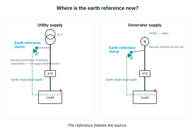
Now switch to the generator, and ask again. Where is the earth reference now? It has to move. The utility neutral is gone — the changeover disconnected it — so unless the installation provides a new reference at the set, the system is floating. And a floating system will not clear a first earth fault cleanly: there is no low-impedance path back to a reference to drive the protection. That is the fault that lingered in the opening.
So the rule underneath everything is easy to state and easy to get wrong: the reference must follow the source. When the generator becomes the source, its star point becomes the reference. The rest of this guide is getting that right and proving it.
Choosing the neutral-earthing arrangement
The generator neutral is the star point of the alternator windings. Earthing it does two jobs at once: it gives earth-fault current a defined path so the protection can see it, and it holds the healthy phases down during a fault instead of letting them swing up and stress the insulation.
For a normal low-voltage building set, the answer is solid earthing — the star point bonded straight to the installation earth. Simple, a clean signal for the protection, and a match for the TN arrangement most UAE buildings run. For the mid-rise building in our example, that is the choice.
Two disciplines come with it. First: one bond, in one place. The neutral takes its earth reference at exactly one point — and the next section shows how much weight that word "one" carries. Second: know when solid is not the answer. As machines get large, and especially at medium voltage, a bolted terminal fault can burn the stator iron before anything trips. There the arrangement changes to resistance earthing — a neutral earthing resistor holds the earth-fault current to a controlled value, protecting the machine while still giving the protection something to measure. For the LV building set, solid earthing stands.
Three-pole or four-pole: the decision that changes everything
This is the pivot of the guide, and it is nothing more than the reference question asked at the instant of transfer. Where is the earth reference now — during the change-over?
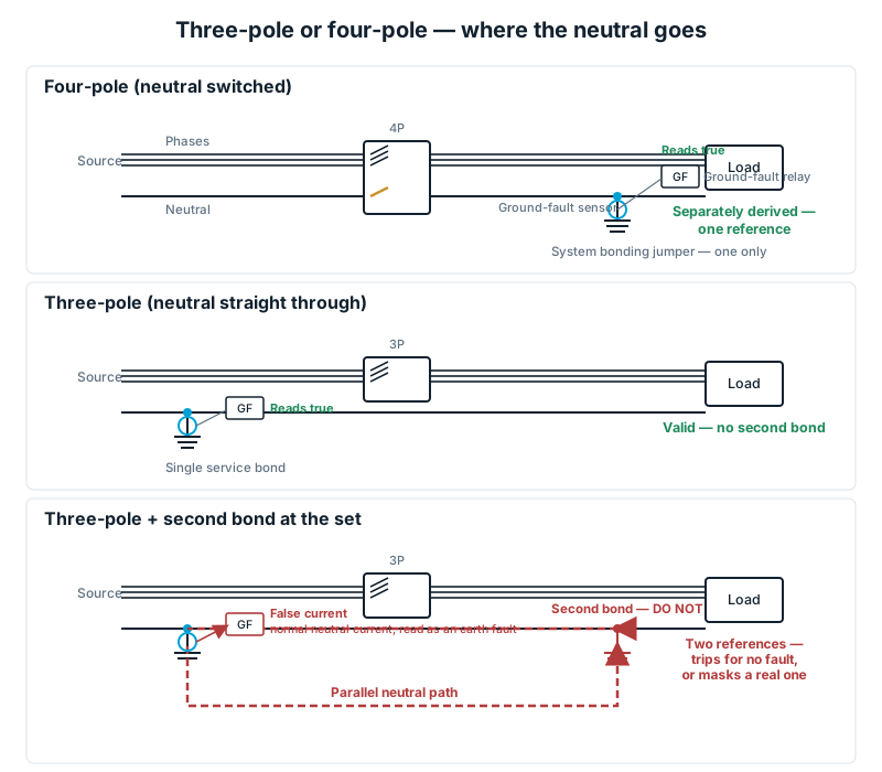
A changeover switches the phases. The real question is whether it also switches the neutral. A three-pole changeover leaves the neutral straight through — one continuous conductor from utility to load to generator. A four-pole changeover switches the neutral as well, so the load neutral ties to the utility neutral or the generator neutral, never both.
Switch the neutral, and the generator stands on its own: neutral earthed at the set, it becomes what the standards call a separately derived system — a source with its own reference at its own star point. The US code (NEC 250.30) names that idea cleanly, but you design to the UAE Wiring Regulations and IEC. Same concept, local authority.
Now the trap — the one we find most on site. Leave a three-pole changeover and also bond the generator neutral to earth at the set, and you have two earth references tied together through the neutral. Neutral current stops returning on the neutral alone; part sneaks back through the earth path between the two bonds. That is a parallel neutral path — current on the earth system that has no business being there, and a false signal into any ground-fault sensing on the main, so the protection either trips for no fault or fails to trip on a real one. It is the single most common way a scheme passes every test on the utility, then fails on the first fault on the set.
So the rule is clean:
- Ground-fault protection on the main, or the generator neutral bonded at the set? → four-pole. Separately derived, earthed once, at the set.
- Neither — a single service bond kept, no second bond at the set? → three-pole can be valid — but then do not add a second earth bond at the generator. One reference.
One four-pole detail only shows up on site: the switched neutral has to overlap through the transfer, or the load is left with an open neutral for a moment — floating, voltages going unbalanced. We prove that overlap at commissioning. For our example — ground-fault protection on the main, set earthed at the star point — the answer is four-pole, separately derived, earthed once at the set.
Protecting a single set: the core philosophy
Now protect the machine, and start from one fact that catches a lot of engineers out: a generator is not a transformer when it comes to fault current.
Feed a fault from the utility and the current is large and stays large. Feed it from a generator and it jumps to roughly three times full-load for a moment, then decays back toward normal within a couple of seconds as the excitation gives up. So plain overcurrent — the kind that guards a distribution feeder — picks up on that first surge and then drops out as the current fades, before it has graded with anything downstream. It lets go of the fault. That is the relay that "wouldn't hold": watch it once and you stop trusting bare overcurrent on a set.
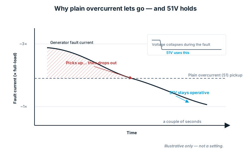
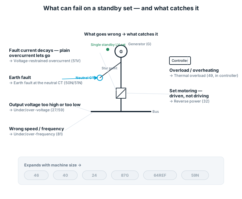
Build the schedule around that decay. Because plain overcurrent lets go, the set gets voltage-restrained overcurrent (51V) — it leans on the voltage collapse every real fault brings, so it stays picked up while the current sags. Earth faults it watches at the neutral CT on the star-point conductor (50N / 51N) — an element that only tells the truth if the reference sits where you think it does, which is why the earthing decision came first. As the source, the set must police its own output too: under- and over-voltage (27 / 59) and under- and over-frequency (81) guard the building against a machine that is drifting. Reverse power (32) catches the set being driven instead of driving — motoring off another source — essential the moment there is a parallel path. And thermal overload (49), in the engine-and-alternator controller (DSE, ComAp, DEIF and the like), stops it carrying more than it can for longer than it should.
That is a complete, honest core for a single standby LV set — an experienced engineer should read it and find nothing essential missing.
How the philosophy grows with the machine
It does not change as sets get larger — it extends, and it helps to know the ladder is there. Push into large-LV, medium-voltage, paralleled or mission-critical duty and the schedule earns more elements, each for a specific way a bigger machine hurts itself: negative phase sequence (46) for the unbalance that overheats the rotor, a dedicated thermal overload (49), loss of excitation / field (40), overfluxing (24, volts-per-hertz), generator differential (87G) for internal winding faults, restricted earth fault (64REF) for a fault close to the star point, and neutral displacement (59N) on resistance-earthed systems. Each earns its place with size and consequence; the full treatment belongs to a machine-protection companion, not here.
What changes when you parallel
Put a second set on the bus and the question sharpens. Where is the earth reference now — with two star points?
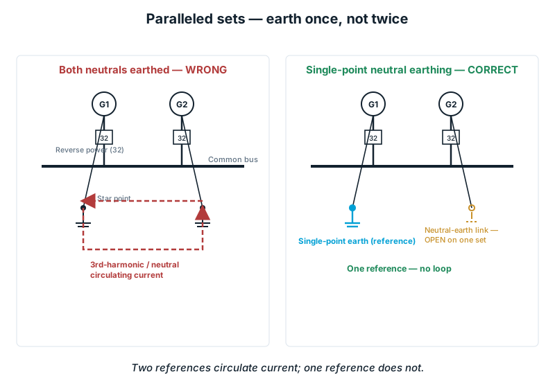
Earth both neutrals solidly and you are back to two references tied through the shared neutral — and this time you also invite circulating current between the star points, third-harmonic current chasing round the loop and heating conductors for nothing. The cure is single-point neutral earthing: one star point earthed at a time, or a dedicated arrangement holding the single bus reference. One reference, always. Paralleling also makes reverse power (32) non-negotiable — a set that loses its engine will motor off its neighbour and wreck itself. Check-synchronising (25) and load-sharing belong to the synchronisation guides.
Then the biggest step. If the scheme ever closes onto the utility — closed transition, or parallel export — the answer flips. Whose reference governs now? The utility's. Your set must not force its island reference onto the grid, and it must drop off fast and cleanly the instant the grid disappears. That is mains-decoupling protection — rate-of-change-of-frequency and vector shift (81R / 78) — and you do not parallel with the DEWA or Etihad Water & Electricity network without their approval. That approval is a design gate, not an afterthought.
The UAE authority layer
Everything above stands on a local foundation. The UAE Wiring Regulations (2020) and the DEWA and Etihad Water & Electricity regulations are the governing authority here, with IEC behind them for the installation and earthing principles (IEC 60364 and its earthing parts) and IEEE guidance (notably C37.102) behind the generator protection.
Two of those requirements shape the whole scheme, and both are the reference question in official language. The authority earths the neutral at its substation and expects it earthed there and not again in your installation — precisely why a careless second bond at the set causes so much grief. And the consumer provides an earth-electrode system to the required standard, which is the reference the installation owns once the set is the source. Parallel with the grid and authority approval becomes mandatory. Design to the local regulation first, reach for IEC and IEEE for the detail, and treat NEC only as a way to name a concept.
Proving it on site: the commissioning workflow
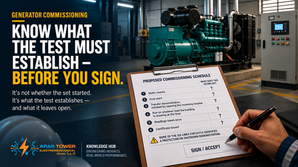
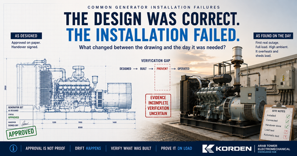
A correct drawing is a promise. Commissioning is where you find out whether the site kept it. This is the sequence an experienced commissioning engineer actually follows — every step the reference question again, asked with an instrument instead of a pen.
- Verify the neutral-earth bonding philosophy. Confirm the site matches the design — solid or resistance, three- or four-pole, exactly one neutral-earth bond in the right place. Most earthing faults are decided here.
- Verify earth continuity. Prove every enclosure, star point, earth bar and electrode is truly connected, protective conductors continuous and correctly terminated.
- Verify earth resistance. Measure the earthing-system resistance against the authority and design limit — the quality of the reference itself.
- Confirm the changeover neutral switching. For four-pole, prove the neutral transfers and overlaps so the load never sees an open neutral — the floating-neutral trap, tested.
- Verify CT polarity. Confirm every CT, line and neutral, faces the right way — a backward one tells the protection a lie you cannot see by inspection.
- Secondary injection. Inject signals into the relay to confirm each element operates at the intended pickup and time.
- Primary injection. Drive real current through the actual CTs and cabling to prove the whole chain and polarity under load. Reversed CTs are caught here for good.
- Functional relay testing. Exercise each function — 51V, earth fault, reverse power, voltage, frequency — and confirm each trips the right breaker and alarms.
- Simulated transfer testing. Run the utility-loss and return sequence end to end and watch the reference hand over as the source changes — the opening mystery, under control.
- Final operational verification. Load the set, confirm stable operation and clean protection behaviour, and record it all.
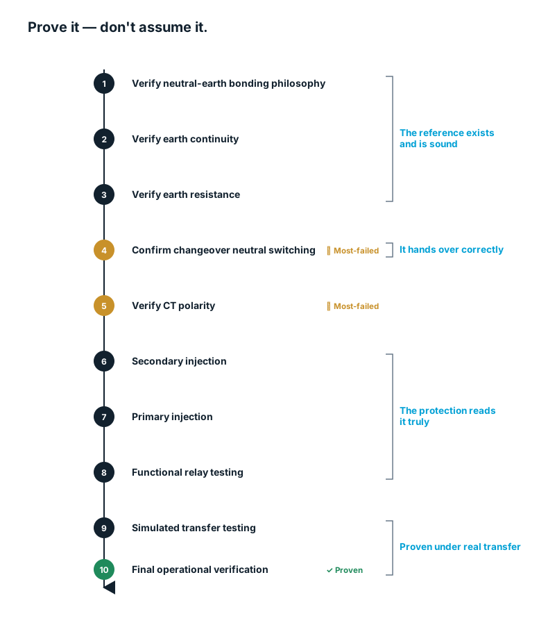
Figure 6 — The ten-step commissioning sequence, and what each stage proves about the earth reference.
Skip steps and the installation still looks finished. It just isn't proven — and the first real fault becomes the test you never ran.
Common earthing mistakes found during commissioning
These are the faults we actually find on site. Read each as a wrong answer to where is the earth reference now?
- A second neutral-earth bond — two bonds where the design allows one. The classic parallel-path maker: nuisance trips and desensitised earth-fault protection.
- A floating neutral — no reference when the set is the source, or a neutral left open through the transfer. First faults that won't clear, and unbalanced voltages.
- The wrong changeover pole count — three-pole where four was needed, or a four-pole wired as if it were three. The reference in the wrong place at the wrong time.
- A neutral CT in the wrong position — on the wrong side of the neutral-earth bond, say, so it never sees true earth-fault current.
- Reversed CT polarity — the protection reads current backwards; reverse-power and directional elements mis-operate. Invisible to the eye, obvious to primary injection.
- Incorrect earth-conductor termination — a protective or star-point conductor loose, under-sized, or landed on paint. Continuity that measures fine and fails under fault current.
- Parallel neutral paths — neutral current sharing between the neutral and the earth system from a bonding error upstream. Objectionable current the whole time.
Every one is cheap to fix at commissioning and expensive to find after handover.
What to check on the single-line: a consultant's drawing review
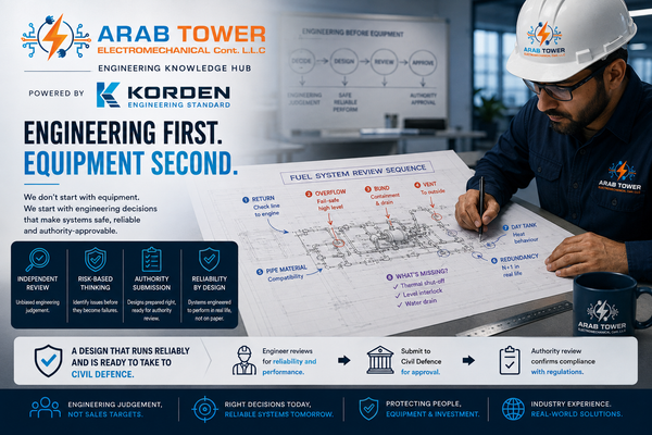
You can catch most of those faults at the design stage. When a generator single-line lands on your desk, run down this list — the drawing-stage mirror of the commissioning workflow:
- ✔ Neutral-earth bond shown clearly, in one defined place.
- ✔ Earth electrode system present and specified.
- ✔ Neutral CT shown, in the correct position for earth-fault sensing.
- ✔ Changeover pole configuration — three- or four-pole — stated and consistent with the earthing decision.
- ✔ Generator protection relays and functions scheduled (51V, 50N/51N, 27/59, 81, 32 as a minimum).
- ✔ Earth bar shown, with what lands on it.
- ✔ Protective-conductor routing traceable from enclosure to bar to electrode.
- ✔ Earthing labels and the neutral-earthing philosophy noted on the drawing, so the next engineer inherits the decision instead of guessing it.
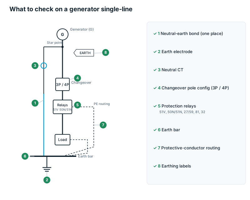
If any of those is missing or ambiguous, you have found the fault before it was built.
Which path is your project?
The whole guide reduces to one habit: at every state, ask where is the earth reference now?
- Utility supply — reference at the authority substation; keep the installation to a single service bond.
- Generator supply — the reference moves to the set; solid earthing for the LV building set, resistance earthing for large and medium-voltage machines.
- The transfer — ground-fault protection on the main, or a bond at the set, means four-pole, separately derived, earthed once; otherwise three-pole with no second bond.
- Parallel generators — single-point neutral earthing, reverse power essential, protection extended with machine size.
- Utility-parallel — the grid's reference governs; add mains decoupling and get authority approval before you close.
- Commissioning — prove the reference is where the design intended, in ten steps, before handover.
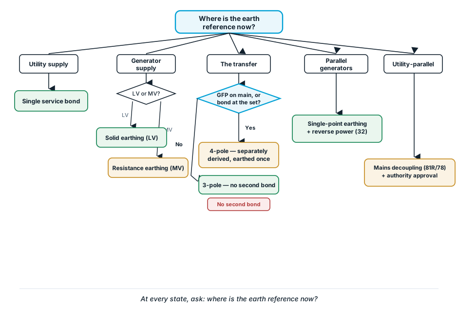
Everything in generator earthing and protection comes back to one fact: the earth reference moves the moment the generator becomes the source. Design for it at every state and the protection looks after itself. Miss it at one, and the installation waits quietly — through every test, right up to the first real fault — to tell you where it went.
Talk to our engineers → If you are specifying or reviewing a generator earthing and protection scheme, send us your single-line and your earthing philosophy. Arab Tower will review the neutral-earthing arrangement, the changeover pole count and the protection schedule, and — once built — test, commission and hand it over. We would rather tell you your scheme is sound than find out otherwise on the first fault.
Arab Tower Electromechanical Cont. L.L.C. — supply, install, test, commission and hand over of electrical power systems across the UAE and internationally, since 2003.
Go deeper: Generator Room Design · Generator Synchronization Explained · Common Generator Installation Failures — companion guides (linked as each goes live).