Generator Load-Bank Testing: What It Actually Reveals — and What It Leaves Untested
A load-bank test is an instrument to read against a specific claim, not a duration to run out. What it proves, what it leaves untested, and what to demand before the day.

A commissioning schedule for a critical facility carries one line: “Load-bank test, four hours at 100% at the generator output terminals.” No other loading test is scheduled. The certificate for the job depends, more than any other line, on that one.
Read as a duration to run out — four hours, 100%, done — the line looks unarguable. But the same line, read against what it is actually being asked to prove, may prove much less than the certificate later gets quoted for. The test may evidence that the generating set carried the applied electrical load for four hours at the conditions actually tested. It does not automatically evidence rated capability at the design ambient, ATS transfer, load pickup on the emergency-power path, or the alternator’s behaviour at the lagging power factor it is rated for. Which of those matter depends on the claim being made from the test — and that is a decision that has to be made before the test, not after.
A load-bank test is an instrument to read against a specific claim, not a duration to run out.
What this guide covers, and what it does not
This guide is for the engineer looking at a proposed load-bank test — a line in a commissioning schedule, an annual test on a critical facility, or a rental proposed after a set has misbehaved — who has to decide whether the scope will actually prove what is being claimed from it. It covers how to articulate the claim, what a load bank does and does not control, how the electrical connection point and the physical test configuration together decide what is inside the test, what each type of load bank exercises on the set, how to read the proposed test as an instrument, and — in the decision tree at the end — how to judge the whole scope for the reader’s own project.
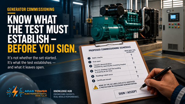
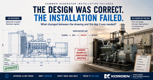
It does not cover the full commissioning sequence, which is R7’s guide. It does not cover the mechanism, prevention or recovery of wet stacking, which belongs to R10. It does not cover hard-load or step-load derivation (R1), no-start diagnosis (R9), why a correct design fails on site (R5), or paralleling and synchronising commissioning (E4, with faults in R6). It is not a buyer’s guide to load-bank equipment.
The four questions
Every load-bank test the reader will ever face can be judged by four questions in this order, and they are the whole method of this guide.
- What is being claimed from this test?
- What does the test actually control?
- Where is it being connected — and in what configuration?
- What does that put inside the test, and what does it leave outside?
The questions are simple and the discipline is: they are answered for this test, on this project, against this claim. No universal answer exists to any of them.
The rest of this guide applies them. It does not restate them.
Why the claim comes first
The single most common failure of load-bank testing is not that the test was too short, or the load too small, or the wrong type of load bank was hired. It is that the claim was never articulated, and the certificate that came out of the test was later quoted to support whatever anyone happened to want.
Different candidate claims for the same set — rated kW at the test-day ambient at unity power factor · rated capacity at the design ambient · ATS transfer and installed-path load-carrying · alternator capability at the specified lagging power factor · compliance with a specific adopted clause · a warranty run-in — each demand a different combination of load-bank type, connection point, test configuration, duration and record. Read against a duration, the same “four hours at 100%” line means the same thing to all of them. Read against the claim, it changes character completely — adequate for one, insufficient for another, wrong instrument entirely for a third. Before duration, load step or connection is discussed, the claim has to be written down.
Controlled loading, uncontrolled ambient
A load bank is valuable because it does one thing well: it applies known electrical loading independently of what the building can offer on the day. Chosen kW, chosen kVAR (if the bank is reactive-capable), chosen step profile, chosen duration. That is what it controls.
It does not control the site ambient. Whatever the ambient is on the test day is the ambient of the test. Building load on a February morning cannot prove August; a load-bank test on a February morning cannot prove August either, simply because the load came from a load bank. What the test evidences is what happened at the test-day ambient. That is the important asymmetry, and the reader who misses it will over-read every result.
Two consequences follow, and both are engineering discipline the article does not compromise on.
First, the test-day ambient must remain traceable to the corresponding test period and results — as a timestamped environmental trend, or as an equivalent properly-associated record — so that any later reader can interpret the result within the conditions it was recorded under. It does not have to be repeated beside every individual measurement; it does have to be retrievable against every measurement.
Second, the design-condition claim has to be treated with care. A load-bank result at a mild ambient is direct evidence of what the set did at that ambient. Manufacturer derating data at the design ambient, ventilation design, room temperature-rise calculations and specified capability at the design condition are engineering evidence that may support a design-condition claim. Those two things — demonstrated by test and supported through engineering evidence — do not merge into a single “demonstrated” claim. They are two pieces of evidence, of different kinds, that a competent engineering judgement reads together.
Two boundaries: electrical connection point and physical test configuration
This is the section of this guide the market misses.
The electrical boundary of the test is not a line drawn on a single-line diagram between “upstream” and “downstream” of the load-bank connection point. It is the actual current path created between the generating source and the load bank under the test switching configuration — which switchgear is closed, which is open, which alternate sources are locked out, which bypass or isolation is in place. Only equipment and functions actually carrying or controlling that test current can be claimed from the loaded test — and functional claims (an ATS transfer, a sequenced load pickup, a protection operation) still require the function itself to be exercised, not merely to sit inside the current path.
Read that way, a load bank at the set’s output terminals imposes electrical loading on the alternator and the engine, and on any switchgear the current-path passes through in that test configuration. It does not exercise an ATS transfer sequence, downstream distribution beyond the connection point, or the behaviour of protective devices under any condition the test does not create. Those functions or portions of the installation are either outside the test current path, or inside it but not exercised by the test as configured — and either way, they cannot be claimed from it.
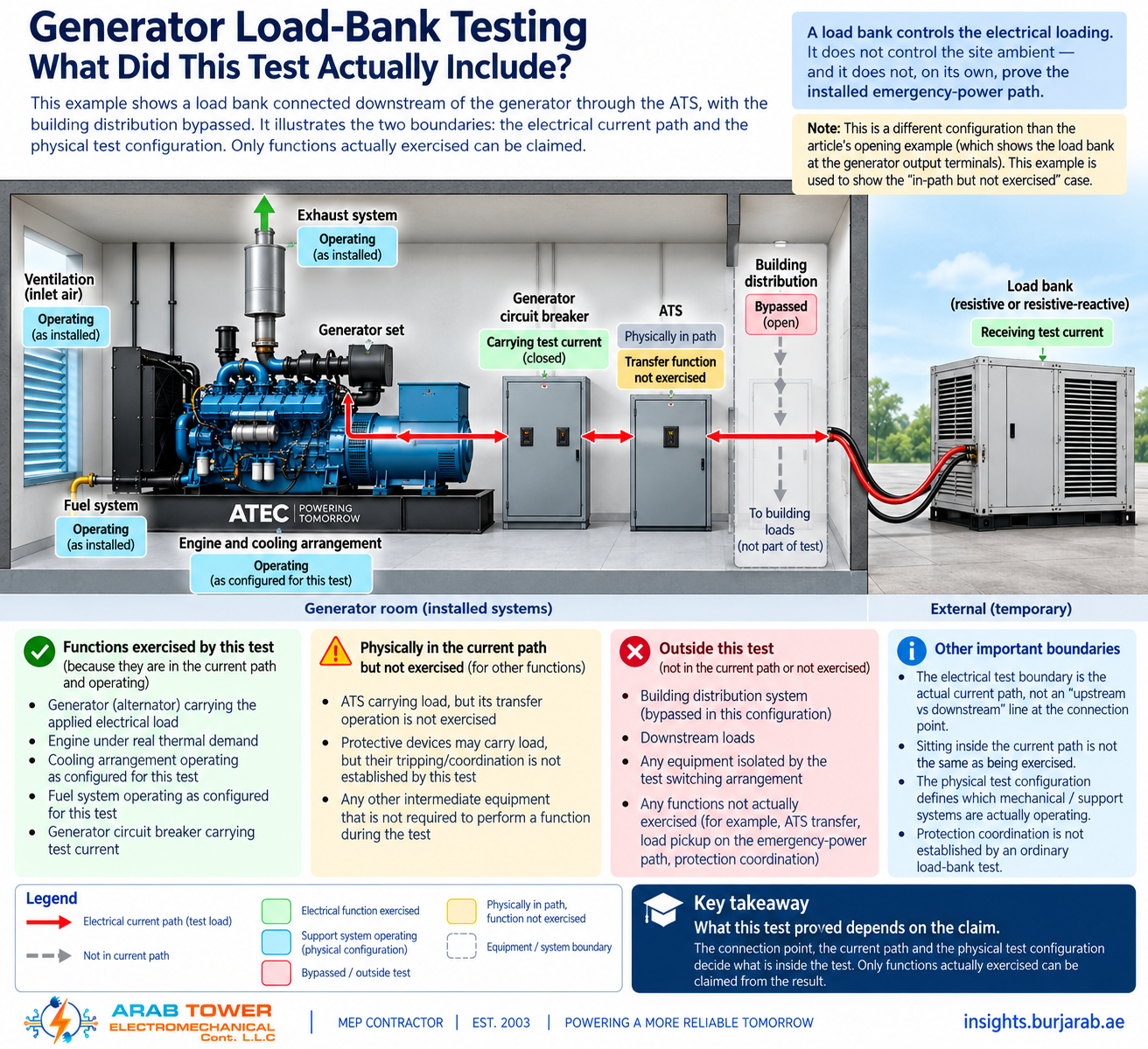
Whether the installed cooling, ventilation, fuel and exhaust arrangements are actually being exercised is a separate question that the electrical connection point does not answer on its own. It depends on the physical test configuration on the day. Final exhaust connected, or a temporary bypass run out through a door? Installed room ventilation live, or doors propped and radiator airflow altered? Installed fuel supply from the day tank, or a temporary tank alongside the set? Installed radiator, or a remote radiator swapped in for the test? Each of those changes what is really being exercised, and none of them shows on the electrical single-line drawing.
The governing rule the article rests on:
Electrical connection point defines the electrical test boundary; test configuration defines which mechanical / support systems are actually being exercised.
Both bound the claim. Both are recorded. Both have to serve the claim, or the certificate will later be quoted for things it did not establish. This is also the reason protection coordination cannot be claimed from an ordinary load-bank test. Coordination is fundamentally about selective behaviour under abnormal / fault conditions, and it is established by protection studies, settings, device curves and — where appropriate — functional or injection testing. A load-bank test at operating load can reveal a device that maloperates at legitimate current, and can evidence that the loaded path carries the prescribed current without unwanted operation. It does not by itself establish coordination.
More generally: only functions actually exercised by the test can be claimed as demonstrated. Connection location alone does not prove ATS operation. A downstream connection point may bring more of the installed path into the loaded circuit — but only functions the test actually exercises, in the intended configuration, can be signed for.
Types of load bank — what each exercises on the set
There are three types the reader will meet on generator work — resistive, reactive, and combined resistive-reactive. The distinction that matters is not what they look like in a rental catalogue; it is what each exercises on the set.
A resistive load bank applies electrical loading at approximately unity power factor. It intentionally imposes no reactive loading; the actual measured power factor at the machine terminals may still differ slightly from a mathematical 1.000 depending on the connected system and instrumentation, but the bank is not delivering the lagging condition the alternator was rated for. A resistive-only bank therefore places real thermal demand on the engine and on the cooling arrangement actually operating during the test, and it exercises the alternator only at essentially unity power factor. It does not exercise the alternator’s reactive capability, the voltage regulator’s response under lagging conditions, or the excitation system at whatever lagging power factor the machine’s rating specifies.
An inductive reactive load bank imposes lagging reactive demand, allowing the test to exercise the alternator’s current, the excitation system and the AVR’s behaviour under a specified lagging power-factor condition. A combined resistive-reactive load bank allows simultaneous kW and kVAR loading, so that the machine can be exercised at a specified apparent-power and power-factor condition together.
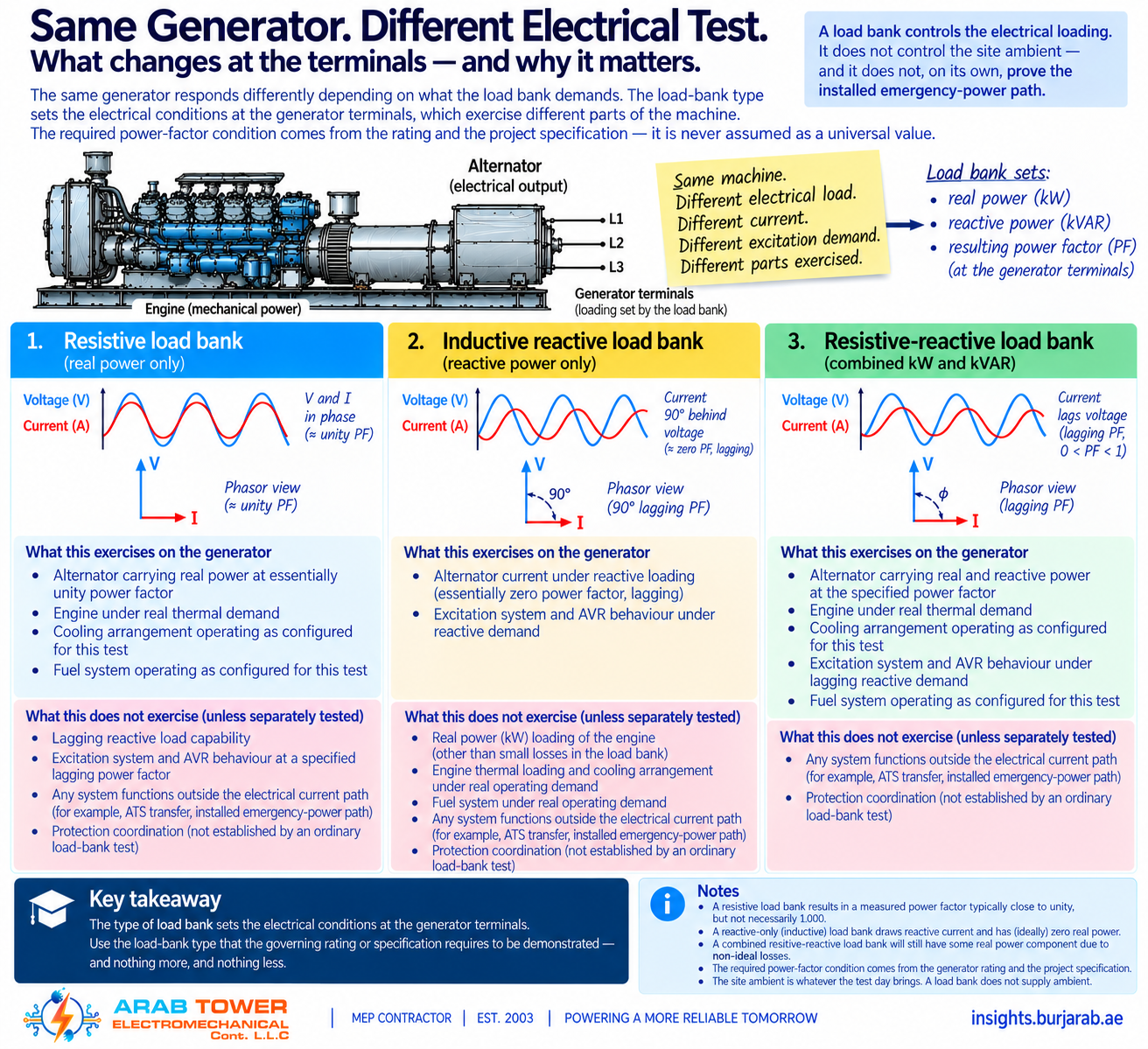
Which one is appropriate is a claim-driven decision. If the claim is the set carried rated kW at unity power factor at the generator terminals, a resistive bank is adequate. If the claim is the alternator delivers rated capability at its specified lagging power factor, a resistive-only bank cannot deliver that. The power-factor condition to be demonstrated comes from the applicable rating and specification for the machine — not from a universal assumption about what “rated” means. Never asserted, never assumed. Read it off the rating plate and the specification, and match the instrument to it.
Reading the proposed test as an instrument
Once the claim, the boundaries and the instrument type are settled, the proposed profile can be read stage by stage — warm-up, step application, sustained run, a reactive segment if the bank supports it, a deep-load segment if the investigation calls for it, shutdown — and each stage judged for what it evidences at this connection point, in this configuration, against this claim.
The record has two layers, and they must not be collapsed into one.
The governing minimum measurements are those the applicable rating, the project specification, the adopted-code clause or the manufacturer’s test requirement mandate for the claim. These are non-negotiable. If the claim is compliance with an adopted-code clause, the measurements the clause names are the minimum. If the claim is a warranty test, the measurements the manufacturer requires are the minimum. They come from the governing document, not from a house checklist.
The additional diagnostic observations — trend of exhaust temperature, coolant, room air-inlet versus outlet temperature difference, voltage and frequency behaviour on step application, alternator behaviour where instrumented, fuel behaviour — are useful where the instrumentation is available or the investigation warrants them. They are not a universal minimum. A diagnostic observation smuggled in as a required measurement is the same failure mode, in reverse, as an absolute duration written into a schedule with no rationale.
Alongside every measurement, the test-day ambient must remain traceable and the connection point and physical test configuration must be recorded. Years later, only a record that carries those together will let another engineer read what the test actually evidenced.
Which scope does your project need?
The same load-bank line reads differently against different claims. Here is how to route the one in front of you.
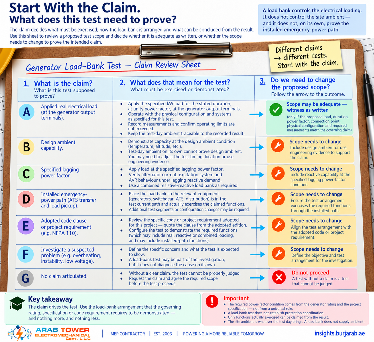
A · The reader must evidence the generating set carried the applied electrical load for the stated duration, at unity power factor, at the generator output terminals, in the installed cooling / ventilation / fuel / exhaust configuration recorded, without exceeding the applicable monitored operating limits. A resistive-only load bank at the generator terminals can evidence that. Settle duration and step profile against the manufacturer’s requirement and any adopted specification. Require the connection point and the physical test configuration to be recorded. Require the test-day ambient to remain traceable. Accept the schedule as written if the claim is honestly stated at that level, and do not let the certificate later be quoted for more.
B · The reader must support the installation’s rated capability at the design ambient. A load bank cannot supply the ambient — the design-condition claim cannot be demonstrated by test on a mild day, whatever the connection point. Separate what the recorded load-bank result is direct evidence of (the set carried the applied load at the test-day conditions) from the wider engineering evidence that may support / validate design-condition capability — manufacturer derating data at the design ambient, ventilation design, room temperature-rise calculations, cooling-air path, specified capability at the design condition. Read them together; do not merge them into a single “demonstrated”.
C · The reader must evidence the alternator delivers rated capability at its specified lagging power factor, and the governing rating or specification requires that capability to be demonstrated by test. A resistive-only bank cannot deliver the lagging condition. The test arrangement then needs reactive capability sufficient to impose the specified kVAR or power-factor condition — the test instrument follows the requirement, not the other way around. Read the required power-factor condition off the machine rating and the specification, never asserted as universal, and record voltage-regulator behaviour and alternator temperature rise during the reactive segment.
D · The reader must evidence ATS transfer operation, sequenced load pickup, or installed-path load-carrying. A generator-terminal load-bank connection alone cannot establish this claim. The test may need more than one segment or switching configuration — a generator-terminal load-bank segment may remain appropriate for one part of the claim, while a separate downstream or functional test configuration is required to place the relevant equipment inside the test current path AND to exercise the specific functions being claimed. Those functions have to be exercised under the intended test conditions to be claimed; sitting inside a current path is not the same as being exercised.
E · The reader must satisfy a specific adopted code clause on periodic loading or load-bank testing — for example, where NFPA 110 is adopted contractually or by code for the project, Chapter 8 sets out routine maintenance and operational testing requirements for emergency and standby power systems, including provisions for periodic exercise loading and for a load-bank test where the routine-exercise loading criterion is not met. The applicable provisions are edition-specific and vary by system classification and by other factors set out in the standard itself. Quote the clause that governs your project from the adopted edition; do not paraphrase, and do not extend a specific EPSS requirement into a universal UAE rule. Periodic testing under such a clause evidences continued operational capability under the prescribed test conditions, in service; it does not substitute for what commissioning-stage proof should have established, and its purpose is not reduced to auditing the maintenance regime.
F · The reader is investigating a set that has misbehaved. Controlled loading via a load bank is one instrument within a wider investigation, not a standalone answer. Articulate what the load-bank test could confirm or refute for the working hypothesis. If the working hypothesis is a field-installation pattern, R5 owns it. If the working hypothesis is a failure to start, R9 owns it. If the working hypothesis is a long-term light-load duty cycle and its consequences, R10 owns the mechanism and the recovery criteria; a load-bank test may support the investigation but does not itself establish that recovery has been achieved.
G · The reader is being asked to accept a test where no claim has been articulated. Send it back. A test without a claim is a test that cannot be judged.
Each branch ends at the same action, differently weighted: before the day, send us your generator rating, the application (standby / prime / continuous), the site ambient, the intended load-bank connection point, the physical test configuration, and the proposed test scope. We will tell you what it will prove — and what it will leave unproven. That answer is sometimes the proposed scope is adequate — witness it as written. It is written that way when the claim is honestly stated at the level the test can carry.
Engineering References
ISO 8528-5 (current edition 2025), Reciprocating internal combustion engine driven alternating current generating sets — Part 5: Generating sets — used for generating-set design and performance criteria, including load-acceptance and transient performance classes, as the acceptance criterion a step-load segment may be asked to demonstrate. It is not itself a load-bank test procedure. ISO 8528-6:2023, Reciprocating internal combustion engine driven alternating current generating sets — Part 6: Test methods — where its clauses cover the intended test, this is the closest ISO document to load-bank test method for the set; specific clauses are read against the standard’s own text before any clause-level claim is made. NFPA 110 (current edition 2022, unless a different edition is adopted for the project), Standard for Emergency and Standby Power Systems — for emergency and standby power system installation acceptance and routine testing, where the standard is adopted contractually or by code; Chapter 8 governs routine maintenance and operational testing. The applicability condition is stated every time it is cited, and the specific provisions that govern your project are read from the adopted edition and quoted, not paraphrased. IEC 60364-6, Low-voltage electrical installations — Part 6: Verification — the discipline behind the electrical checks. Abu Dhabi Department of Energy Electricity Wiring Regulations 2020, where applicable — authority and distribution-company requirements differ by emirate and project. UAE Fire and Life Safety Code and Civil Defence requirements where fuel autonomy and run-time during test engage the fuel-system approval. Manufacturer commissioning requirements, operating limitations and warranty test requirements are always among the binding documents, and are frequently the strictest.
Arab Tower is an MEP contractor in the UAE, established in 2003, with a current testing and commissioning capability that includes generator load-bank testing — commissioning-stage, periodic, and as one instrument within wider investigations. Before you accept, refuse or specify a load-bank test, send us your generator rating, the application, the site ambient, the intended connection point and physical test configuration, and the proposed test scope. We will tell you what it will prove, and what it will leave unproven.
Talk to our engineers → · or see our Testing & Commissioning service.
Go deeper: Generator Commissioning: What the Test Must Establish Before You Sign (R7) · wet stacking and long-term light-load operation (R10, forthcoming).