Generator Room Design: How to Design a Diesel Generator Room for a UAE Building
A correctly sized generator that trips on high temperature every July is almost never the machine — it is the room. A practical guide to designing a generator room that works in the UAE: ventilation, exhaust, fuel and Civil Defence.

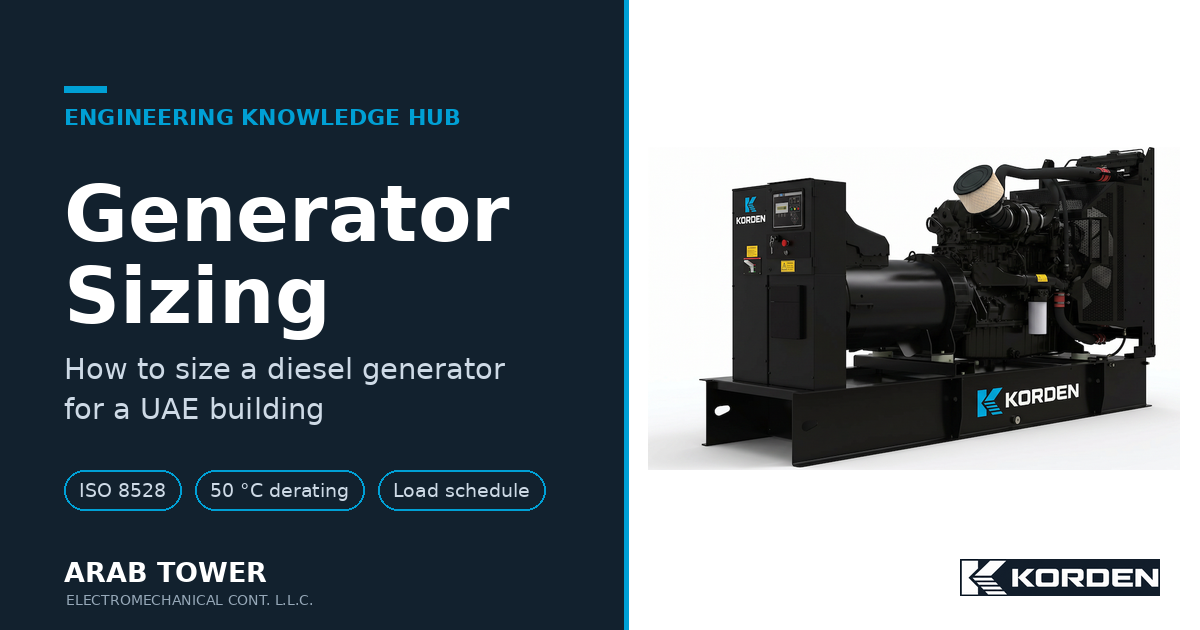
A generator is installed in a new building. It is the right size — the sizing was done properly, the load bank passed, and through the cooler months it runs without a complaint.
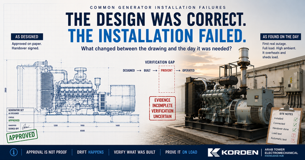
Then July arrives. The same set, on the same load, starts tripping on high engine temperature. Nothing on the machine has changed. No fault code points to the engine. Swap the set for an identical one and the problem stays.
The generator was never the problem. The room was.
The room is the right size on the drawing — the set fits, the clearances are there, it looks complete. But a running diesel generator throws off an enormous amount of heat, and it needs to move a large volume of air to carry that heat away. If the room cannot move that air, the machine sits in its own hot air and slowly cooks — in winter it copes, in a UAE summer it does not.
So here is the shift this guide asks you to make. A generator room is not a space that stores a machine. It is an air and heat system that happens to contain an engine — with an exhaust, a fuel store and a noise source built into it. Design the room as an air system first, and every other decision falls into place. Design it as a box that the set fits into, and you will meet it again in the first summer.
The single rule everything below serves: cool air enters low at the cool (alternator) end, sweeps across the set, passes through the radiator, and leaves — hot — through a discharge that carries it straight outside. The cooling air makes one pass and goes. When hot air is instead released loose into the room, it circles back to the intake, the incoming air heats up, the radiator draws warmer and warmer air, and the set slowly overheats. Keep the pass clean and one-directional and the room works; let it short-circuit and no amount of set quality saves it.
What is this guide for — and what does it hand to other guides?
It settles enough to judge whether a room design will work: what the room really has to do · where it can go and what fights for the space · the real clearance and removal envelope · ventilation and heat rejection at 50 °C (the section that most often fails) · the exhaust back-pressure budget · the fuel arrangement and what Civil Defence expects · acoustics and the airflow it costs · vibration and structure · getting the set in and out · a worked example and a guide to your room type.
It deliberately leaves the deep detail to companion guides, so this stays one clear path: how to size the set (that is the guide before this one), the full ventilation calculation and duct design, silencer selection, fuel storage and the Civil Defence submission, and generator earthing and protection. Go there when your project needs the detail.
We size nothing here — we assume the set is chosen. In fact we will carry the exact building and set from the sizing guide, so the two read as one job.
What does a generator room actually have to do?
Strip it back and the room is doing six things at once, and each one can sink it on its own:
- Breathe — take in enough cool air for combustion and cooling, and get the hot air back out.
- Reject heat — keep the room, and the air the engine draws, below the limits the machine needs.
- Get the exhaust out — safely, and within the engine's back-pressure limit.
- Hold the fuel — feed the engine and satisfy the fire code.
- Stay quiet enough — keep noise inside the limit at the boundary.
- Let the set in and out — for installation today and replacement in fifteen years.
Notice that only one of the six is about the machine fitting. The other five are about air, heat, gas, fuel, noise and access — the systems around the machine. That is why a room drawn to the set's footprint plus a clearance is only ever half-designed.
Our worked example: the same mid-rise UAE commercial building from the sizing guide — offices and retail, a basement car park, rooftop chillers, a fire pump, and a small server room on a UPS. Its standby set was sized at 1250 kVA / 1000 kW. The room is to go in the basement. We put it there on purpose: basement is the common UAE case, and it forces every one of the six jobs to be solved at once. If you can design a basement room, the ground-floor and rooftop versions are easier variations of the same thinking.
Generator Room Design Workflow
Design the room in this order. Each step sets the constraints for the next, and reordering it is where most of the rework comes from — ventilation sized before the location is fixed, or a fuel scheme drawn before the removal opening, both tend to be redone.
| # | Design step | Sets / checks |
|---|---|---|
| 1 | Select room location | basement / ground / rooftop / outdoor — decides how hard every other step is |
| 2 | Confirm equipment installation & removal route | the large opening the set enters and leaves by |
| 3 | Determine room size & maintenance access | envelope = set + service clearance + removal route |
| 4 | Design ventilation & heat rejection | radiator + combustion air, held within limits at 50 °C |
| 5 | Design exhaust & verify back-pressure | total ≤ ~90 % of the engine's limit |
| 6 | Design fuel storage & Civil Defence compliance | day/bulk tanks, containment, fusible-link shutdown |
| 7 | Check acoustics & free-area requirements | boundary noise limit vs louvre free area |
| 8 | Verify structural loading & vibration isolation | wet static + dynamic load, anti-vibration mounts |
| 9 | Review cable routing & auxiliary systems | routed clear of the removal path |
| 10 | Final standards & constructability review | NFPA / ISO / Civil Defence, and can it actually be built |
The rest of this guide follows this order, from location through to the constructability review.
Where should the room go — and is the location even viable?
Answer this before anyone draws the room, because the location decides how hard every other job becomes. When you place a generator room, four things have to leave or reach it, and they all compete for the same building:
- Air — a large intake of cool air, and an even larger discharge of hot air.
- Exhaust — a hot pipe to a safe, high discharge point.
- Fuel — a fill point from a tanker, a vent, and the path from bulk storage to the day tank at the set.
- Removal — a clear path, and a large enough opening, to bring the set in and later take it out.
A location is only viable if all four can be solved together. This is where basements get hard. In our building, the set is five floors down: the cool air has to be brought down and the hot air taken back up, the exhaust has to travel up to a safe roof discharge, the fuel sits under the strictest fire treatment, and the rigging path threads past car-park columns. None of that is a reason to reject a basement — most UAE towers run their sets there — but every one of those four has to be resolved before the room is called viable. A ground-floor room close to an outside wall solves the air and exhaust almost for free; a rooftop set solves air and exhaust easily but trades them for structure and access.
We will come back to the room-type choice at the end, once you have seen what each job demands. For now: the basement is viable for our building because all four can be made to work — so we design it.
How big does the room really need to be?
Bigger than the set. That sounds obvious, and it is still one of the most common ways a room is under-drawn — because people size the room to the set footprint plus a maintenance clearance, and stop there.
Two things push the room larger. The first is service access — working space at the control end, room to pull the radiator core, space to reach filters, pumps and the alternator end, and the code clearances around the set (NFPA 110 and NFPA 37 give the working and separation distances; treat them as the floor, not the target). The second, and the one that gets forgotten, is the removal envelope — the space and the opening to take out the largest component you might ever replace, up to the whole set.
Use this as the room-envelope check — the room is the sum of all of it, not the footprint:
Room-envelope checklist (everything the room must hold, beyond the set footprint)
- [ ] Set footprint and plinth.
- [ ] Maintenance clearance on every serviced side — control end, radiator-core pull, alternator end, filters and pumps (NFPA 110 / 37 as the minimum, not the target).
- [ ] A large intake louvre at the cool/alternator end and a large discharge louvre at the radiator end — each roughly the set's width or wider, and full height, and sized on free area (see the ventilation section), because these are the biggest openings in the room.
- [ ] A way to install and remove the set — normally through the louvre wall (a removable louvre bank) or a dedicated large access / knock-out panel, not a personnel door.
- [ ] The exhaust riser position at the engine kept clear (it goes vertically up through the slab or roof, not along a wall).
- [ ] The day tank position at the set and its fuel pipe run to the engine.
- [ ] Cable containment and control-panel space routed so they do not cross the removal path.
One point is worth making plainly, because it is where drawings go wrong: the set does not leave through a doorway. A machine this size is craned or skated in and out through the large louvre opening or a dedicated access panel — usually at the radiator/discharge end — so that opening is designed as the removal route from the outset. In our basement, the plinth position is fixed not by where the set fits, but by where it still fits once you have kept that large opening and a clear path back to it.
Ventilation: can the room reject the heat at 50 °C?
This is the decision that makes or breaks the room, so it earns the most space. Get everything else right and starve the set of air, and the room fails. Get this right and most of the rest follows.
A running diesel generator needs air for two different jobs, and people routinely design for one and forget the other. The scale of the two is the whole point:
The two air demands (our 1000 kW / 1250 kVA set)
| Air the room must move | Rough size for this set | Who sets it |
|---|---|---|
| Combustion air — burned by the engine | ~100 m³/min (≈ 0.1 m³/min per kW) | The engine rating |
| Cooling / radiator air — carries the heat away | ~1,000 m³/min or more (from the set data) | The radiator — the dominant number |
| Heat radiated to the room — off the engine, exhaust and alternator | carried out by the same cooling air | Surface heat of the running set |
Read that table and the design almost writes itself: combustion air is small; the cooling/radiator air is roughly ten times larger and dominates. Always take the radiator airflow from the set's own data sheet — never assume it. Size the room's air path to pass the full radiator flow plus combustion air, and hold the room's temperature rise to a few degrees over ambient. Here is the UAE problem in one line: if the incoming air is already at 50 °C and the room adds another 5–10 °C, the air the engine actually breathes can be pushing 55–60 °C — at or beyond what the machine is happy with. That is exactly the summer trip we opened with.
Now the part almost everyone gets wrong: the size of the hole is not the size of the airway. A louvre's stated size is its gross area. Air only gets through the free area between the blades — and that is a fraction of the gross:
Louvre free area — size on this, not the opening
| Louvre type | Free area (share of gross) | Gross louvre needed for a given clear airway |
|---|---|---|
| Plain weather louvre | ~50% | about 2 × the required airway |
| Acoustic louvre (for noise) | ~⅓ or less | about 3 × the required airway |
So if the set needs, say, 8 m² of clear airway on the intake, a plain louvre must be roughly 16 m² gross and an acoustic louvre roughly 24 m². Design to the stated louvre size instead of its free area and you have silently halved the air the room can breathe. This single number — free area, not gross — is behind a large share of the overheating rooms we are called to.
A worked airflow check — where that 8 m² comes from (same 1000 kW set; figures illustrative).
- Take the radiator (cooling) airflow from the set's data sheet — here about 1,000 m³/min ≈ 17 m³/s — plus roughly 100 m³/min of combustion air on top.
- Choose an intake face velocity through the free area: about 2 m/s keeps the pressure drop and the noise sensible.
- Required clear (free) airway = 17 ÷ 2 ≈ 8 m².
- Convert to a gross louvre using the table above: plain ≈ 2 × 8 ≈ 16 m²; acoustic ≈ 3 × 8 ≈ 24 m².
An opening that size is on the order of the set's own footprint — which is exactly why the intake and discharge louvres are the largest openings in the room, and why sizing them on gross area starves the set. The hot-air discharge needs the same check.
Two more rules earn their place because they decide whether the air actually does its job:
Bring cool air in low, take hot air out high, and make it sweep the machine. Air should enter near the floor at the alternator (cool) end, travel across the set picking up heat, and leave high at the radiator (hot) end. If intake and discharge sit on the same wall, or the discharge is anywhere the intake can draw from, you get recirculation — the room breathes its own hot air, room temperature climbs 10–15 °C above ambient, and the set de-rates or trips. Recirculation is the quiet killer, because it passes every test on a cool commissioning day and only shows itself when the outside air is already hot. The cleanest defence is the single-pass rule from the opening: the radiator discharge is carried straight outside, not released into the room.
In a basement, the radiator usually cannot simply push against a wall. Five floors down, there is no outside wall to discharge through. So you duct the radiator discharge up to grade, or you fit forced-ventilation fans, or — when the air path simply cannot carry the heat — you move the radiator out of the room entirely with a remote radiator at grade or on the roof, leaving only the engine's own heat to ventilate. Which of those you choose is a real engineering decision driven by the building, not a default. For our basement, the honest answer is often a ducted discharge riser plus assisted ventilation, with a remote radiator held in reserve if the riser cannot be made big enough.
What we see on site — rooms ventilated for a comfortable 40 °C rather than the UAE design ambient, with acoustic louvres sized on their gross area. The set is fine, the drawing looks fine, and the room quietly de-rates a good machine every afternoon in July. The fix is almost always more free area and a cleaner, one-directional air path — cheap on paper, expensive once the louvres are built.
Once the room can pass the radiator airflow at 50 °C without recirculating, the ventilation decision is made. Deeper duct, fan and remote-radiator design lives in the ventilation companion guide — go there when the riser sizing gets tight.
Exhaust: will the gas get out within the engine's back-pressure limit?
The exhaust looks like plumbing and behaves like a system. Every metre of pipe, every bend, the silencer and the termination all add resistance — back pressure — and the engine maker sets a hard limit on how much it will tolerate (given as a pressure, often in kPa or inches of mercury). Go over it and you lose power, run hotter, burn dirtier and shorten the engine's life. The trip that gets blamed on the engine is often an exhaust that was never within limit.
So treat the exhaust as a budget. Add up the back pressure of each part and keep the total comfortably under the engine's limit, with margin for fouling over the system's life:
The exhaust back-pressure budget
| Contributor | Typical share of the budget | Design note |
|---|---|---|
| Silencer | the largest single item | grade set by the noise limit (industrial → residential → critical/hospital) |
| Straight pipe | moderate | size for a gas velocity of 20–35 m/s — not the engine flange (matching the flange is a classic under-size) |
| Bends | moderate to high | use long-radius bends; every bend costs, and a long basement-to-roof run adds up fast |
| Termination | small | high above the roofline, rain-protected, and away from the air intake |
| Total | ≤ ~90% of the engine's limit | the remaining margin absorbs fouling as the system ages |
Two of those lines carry a trap. The silencer ties the exhaust to the acoustic decision — the quieter the grade, the more back pressure it costs — so you cannot finalise it without the noise limit (below). And the termination, if it sits near the ventilation intake, feeds fumes and heat straight back into the room — recirculation with a worse smell. Keep the run short and straight, lag it to keep its heat out of the room and off anything anyone can touch, and let it expand on bellows so its growth is not fought by the pipe.
For our basement set, the exhaust is the second-hardest route after air: a long vertical run to a rooftop discharge, sized up for velocity, with long-radius bends, a residential-grade silencer, bellows and lagging — all kept inside the budget with margin to spare. If the budget will not close, the honest moves are a larger pipe, fewer bends, or a lower-restriction silencer traded against noise — not hoping the engine tolerates it.
Fuel and Civil Defence: what arrangement feeds the engine and passes the authority?
Fuel is where the room stops being an engineering problem alone and becomes an approval problem. In the UAE, generator fuel storage falls under the Civil Defence fire and life-safety requirements, and the arrangement has to satisfy the authority as well as the engine. Design it to pass the first time — a fuel scheme reworked after a rejection is one of the most avoidable delays on a project.
Two tanks usually do two different jobs. A day tank sits close to the set and gives it a clean, gravity-friendly feed at the right head — it exists because the engine's own pump often cannot reliably draw from a distant or lower bulk tank, and it also receives the warm fuel the engine returns. A bulk tank holds the autonomy — the hours of run-time the building needs — and refills the day tank. How much fuel you may keep, and where, is exactly what Civil Defence governs, and it is tightest inside an occupied building and a basement.
Run the arrangement against this before it goes to the authority:
Fuel & Civil Defence readiness checklist
- [ ] Day tank at the set — clean, gravity-friendly feed, plus the engine's fuel return.
- [ ] Bulk storage sized to the required run-time and to the Civil Defence limit for that location.
- [ ] Secondary containment / bund under the tanks, sized to hold the contents (commonly ~110%) so a leak is caught, not spread.
- [ ] Thermal fusible link (releases at roughly 70–100 °C) at the day-tank outlet, closing the fuel in a fire and signalling the generator controller to shut the set down safely.
- [ ] Fire-rated separation and rating appropriate to the storage — more so in a basement.
- [ ] Fill point and vent taken to a safe, accessible location, not into an occupied space.
- [ ] The whole arrangement confirmed against the location's Civil Defence limits before submission.
For our basement building, that is a modest day tank at the set with bulk storage handled to suit the Civil Defence limits for the location, containment, the fusible-link shutdown, rated separation, and fill/vent brought to a safe point. The full storage sizing, fuel polishing and the submission itself live in the fuel-and-Civil-Defence companion — here, the decision is simply the arrangement that both feeds the engine and will pass.
Acoustics: how quiet must it be, and what does that cost in air?
Noise is the job that quietly reaches back and changes the ventilation and the exhaust, which is why it belongs here and not as an afterthought. A generator is loud, and the sound escapes the room by three routes: out through the ventilation openings (the biggest path — the same holes you just sized for air), out of the exhaust, and through the structure as vibration.
Start from the limit, not the machine. There is a noise limit at your boundary — stricter at night and stricter still next to residential or mixed-use, which a podium building usually is. Design down to that limit, and accept that each path you quieten costs you somewhere else:
- The ventilation openings are treated with acoustic louvres or attenuators — and, as the louvre table showed, those cut the free area hard, which sends you straight back to grow the openings. Quiet and airflow are in direct tension; you cannot decide one without the other.
- The exhaust is quietened with the silencer grade — which you already paid for in the back-pressure budget.
- The structure is handled by isolating the set from the building (next section), so the noise does not travel out through the slab as a hum.
The engineering point is that acoustics is not a bolt-on. The day you decide the room must be quiet, you have also decided the louvres are bigger, the silencer is more restrictive, and the set must be well isolated. For our podium building, that means acoustic louvres sized for the reduced free area, a residential-or-better silencer inside the back-pressure budget, and proper anti-vibration mounting — the three decisions taken together, not in sequence.
Vibration and structure: how is the set mounted and what must the slab carry?
A generator is a heavy machine that shakes, so two things matter: keeping its vibration out of the building, and making sure the structure carries it.
Isolate the set from the structure. The set sits on a plinth, and between the set and the plinth (or between the plinth and the slab) you put anti-vibration mounts — rubber mounts for many sets, spring isolators where the isolation has to be better, particularly on a rooftop. Skip this and the running vibration travels through the slab as structure-borne noise and, over time, cracks and loosens things around it.
Load the structure honestly. The slab has to carry the set's static weight — and that means wet: the machine, the base-frame, the coolant, and any belly fuel tank full. It also carries dynamic load from the running set. In a basement, on ground, this is usually straightforward. On a rooftop, it is the decision that dominates the whole installation: the structure must be designed for the static and dynamic load, the isolation has to be good enough that the building does not feel the set, and access and weatherproofing get harder — which is exactly why the location choice at the end of this guide matters so much. For our basement set, the plinth and the slab check are routine; the isolation is sized for the podium noise limit rather than for structure alone.
What else has to live in the room?
A few systems share the room and are worth placing early rather than squeezing in later. The power cables run from the set to the changeover and the LV room, on proper containment, on a route that does not block the removal path. The changeover / ATS position is chosen for cable runs and access — near the set or in the LV room depending on the building. The earthing ties into the system per the design (generator neutral earthing and protection are their own decision — see the earthing and protection companion; do not improvise them here). The starting batteries and charger sit at the set, accessible. And if the ventilation section concluded the room cannot reject the heat on its own, the remote radiator and its pipework and fans are part of the room design from the start, not a retrofit.
Keep this section light on the drawing but decided early — each of these, left to the end, tends to land on top of the removal route or the air path.
Can the set be brought in — and taken out again?
This is the decision that gets left until the set is on the truck, and by then it is too late. The room needs a rigging path from where the delivery lands to the plinth, and — the point drawings miss — a large enough opening to pass the set. That opening is normally the louvre wall (a removable louvre bank) or a dedicated large access / knock-out panel, sized for the largest component or the whole set, with a lifting provision or a clear route for a crane or gantry. A personnel door is for access, not for the machine. In a basement, that path threads down ramps and past columns, and it has to exist on the drawing before the structure is poured.
And then the part almost every project forgets: the set will be replaced one day. A room built tight around the machine, with the cable containment and the fuel lines run across the only way out, is a room where replacement means breaking structure. The removal opening from the space section is not paperwork — it is the difference between swapping a set in a weekend and a demolition job. Design the way out at the same time as the way in, and keep it clear for the life of the plant.
Which room is yours?
Our worked example took the basement path because it is the hardest and the most common. Yours may sit elsewhere — and the location changes which job dominates. Find your row:
Room type — what dominates, and what to watch
| Room type | What dominates the design | What to watch for |
|---|---|---|
| Basement plant room (the worked example) | The air path | ducted risers or a remote radiator; a long exhaust run; the strictest fuel fire treatment; rigging and removal access through a large opening |
| Ground floor / dedicated room | Usually the easiest — short air and exhaust paths to an outside wall | still get the louvre free area and recirculation right |
| Rooftop set | Structure + vibration | dynamic load, isolation, wind, weatherproofing, fuel lift, and access |
| Outdoor package / canopy | Siting + foundation | the enclosure is the room (its own ventilation and acoustics); clearances to boundaries and buildings; fuel |
| Containerised | Container heat + exhaust | heat build-up inside the container in a UAE summer; exhaust termination height |
The method is the same across every row; the emphasis moves. Find your row and you know where your hardest work is.
Where does generator room design usually go wrong?
A quick self-check against the ones we meet most:
- The room sized to the set, not to the air — fits on the drawing, overheats in summer. Fix: design the ventilation heat balance first.
- Louvres sized on gross area — the free area is half or a third of that, and the set is quietly starved. Fix: size to free area, especially with acoustic louvres.
- Recirculation — hot air released into the room, or intake and discharge too close. Fix: single pass — cool in low, hot out high, discharge carried straight outside, away from the intake.
- An exhaust over its back-pressure limit — long, bendy, undersized, or an over-restrictive silencer. Fix: budget the back pressure and design under it with margin.
- A fuel scheme that was never going to pass — containment, separation, capacity or the fusible-link shutdown missing. Fix: design to Civil Defence from the start.
- A set that cannot be removed — no large opening or route, so replacement breaks structure. Fix: design the removal opening (usually the louvre wall) with the way in.
- Acoustics bolted on last — bigger louvres and a restrictive silencer discovered after the ventilation and exhaust were fixed. Fix: decide the noise limit early; it changes both.
Every one of these passes a cool-weather commissioning and shows up later. That is the nature of room design — the room is proven by a UAE summer and a Civil Defence inspection, not by the day it is handed over.
Which standards and authorities sit behind these decisions?
ISO 8528-1 (set ratings and site reference conditions), ISO 8528-9 (mechanical vibration), ISO 3046 (engine reference conditions and de-rating for temperature), NFPA 110 (emergency and standby systems), NFPA 37 (stationary engine clearances), NFPA 30 (fuel storage principles), and NFPA 20 where a fire-pump set shares the area. The engine, radiator and silencer manufacturers' application and installation data give you the real airflow, heat rejection and back-pressure limits for the actual machine — use them, because they are specific to the set in your room. UAE Civil Defence fire and life-safety requirements govern the fuel storage, room rating and separation, and the authority connection context (DEWA, SEWA, Etihad Water & Electricity, ADDC) applies where the standby set ties to the supply. Every one of these sets a limit or a method — none of them designs the room for you. That is still the engineer's job, and it is the reason two good rooms for the same set can look different and both be right.
Want a second set of eyes on your room before it is built?
Room design fails quietly and late — in the first summer, or at a Civil Defence inspection, when it is hardest and most expensive to change. That is exactly why a check before the room is built is worth having.
So if you want your room design checked, send us three things:
- the plant-room layout — the room GA with the set, plinth and louvres on it,
- the generator's technical data — heat rejection, combustion and cooling airflow, and the maximum exhaust back pressure, and
- your ventilation, exhaust and fuel scheme.
In return you get a short, plain engineering review — the same method you have just read — covering:
- Ventilation review — the air path and free-area check.
- Heat-rejection assessment — the balance at UAE design ambient (50 °C).
- Exhaust back-pressure review — the budget against the engine's limit.
- Fuel system review — day/bulk tanks, containment and the fusible-link shutdown.
- Civil Defence compliance observations — where the arrangement stands against the requirements.
- Practical constructability comments — access, the removal opening, and what will be awkward to build.
We tell you what we find and why. The review stands on its own, whether or not you build the room with us. Arab Tower designs, installs, tests and commissions generator installations across the UAE and internationally, from the room-design review through to a set running in a room that breathes.
Talk to our engineers → · or see our LV generators.
Go deeper: Generator Sizing · Generator Room Ventilation in Practice · Exhaust System Design · Fuel Systems & Civil Defence · Generator Earthing & Protection.