Common Generator Installation Failures: Why a Correct Design Still Fails on Site
Correctly sized, correctly drawn, every item approved, handover signed — then in the first real summer power cut it overheated and shed load within the hour. The design was correct. The installation failed.

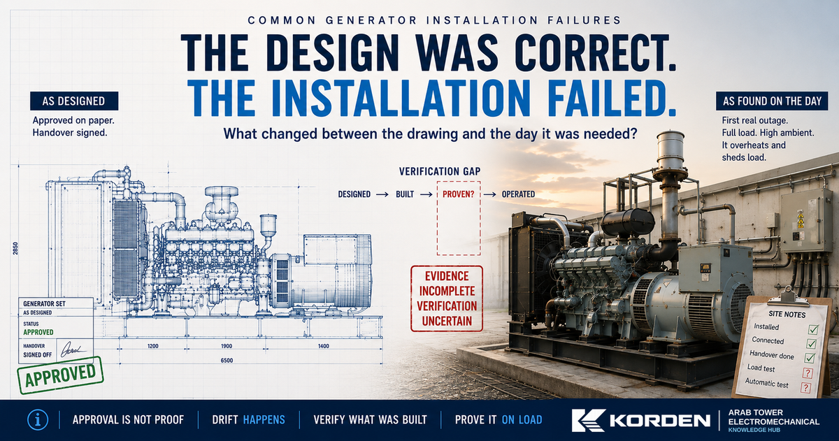
The case below is a composite, built from failures that recur across generator inspections — one installation, one outage, one lesson.
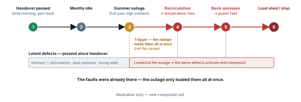
A basement standby set: correctly sized, correctly drawn, every item approved, handover signed. Months later, in the first real summer power cut, it started, picked up the building — and within the hour overheated and shed load.
Nothing on the drawing was wrong. The fault was in what had been built, connected and left behind. The design was correct. The installation failed. That gap — between a correct design and a working set — is this guide's subject.
The five states where reliability is lost
A generator installation is the same set in five states. A correct design guarantees only the first; reliability leaks out in the drift between them, each caught or missed by a different owner at a different gate. A real failure is usually several drifts at once — the model organises the search, it doesn't name one culprit.
| State | The question | Whose gate it is |
|---|---|---|
| As-designed | Is the intent right, and can it be verified? | Design engineer |
| As-submitted | Do the drawings still match the intent? | Reviewing / consultant engineer |
| As-built | Does the install still match the drawings? | Site engineer, supervisor, contractor |
| As-proven | Did commissioning show it works on load? | Commissioning engineer / witness |
| As-operated | Is it left in the state it needs to start on its own? | Facilities / owner |
Watch the state names as we go: every failure below is a drift between two of them that nobody verified.
Airflow — the room that breathes its own heat
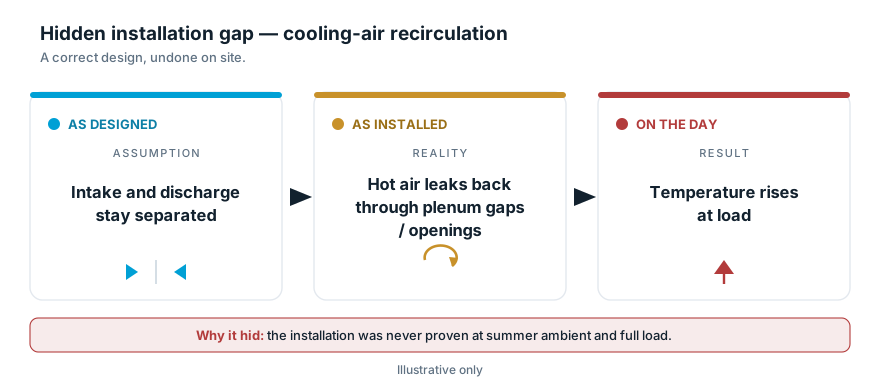
The radiator wasn't undersized; the room was. This is as-built drift at its most common — the room quietly built away from the drawing — and it hides on a mild test day.
- Decide: accept the room only when it rejects the engine's heat at the required load, against the set's cooling / heat-rejection data, at a documented ambient with a peak allowance.
- On the drawing: a louvre schedule that states its net free area and meets the required cooling airflow; intake low, discharge high, separated; radiator discharge ducted.
- Run the number (illustrative; use the set's data): cooling needs ~9 m³/s and the louvre limit is 2.0 m/s → required net free area = 9 ÷ 2.0 = 4.5 m². A 9 m² opening with a standard louvre (~50 % free) gives 4.5 m² — just enough. Swap in an acoustic louvre (~30 % free) at the same opening and it drops to 2.7 m² — 40 % short, and the room now starves the radiator. Net free area = gross opening × free-area ratio.
- On site: is the louvre as fitted the louvre as scheduled? The acoustic swap is invisible to a walk-round. Then check the plenum is intact and penetrations sealed, so hot discharge can't circle back to the intake.
- Prove it: at the required load with ambient recorded, read the radiator-inlet temperature at the maker's defined point and the engine temperatures against the maker's limits — an average room temperature can look fine while the intake quietly recirculates.
It survives handover because it was tested on a mild morning at part load, and a louvre swap looks like a louvre.
Room ventilation design → Room Design.
Exhaust — the back-pressure the site added
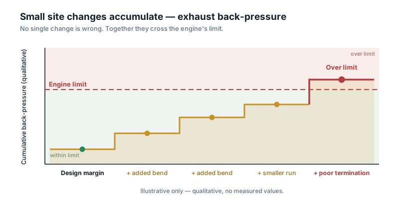
A good exhaust design can be measured out of compliance one bend at a time. This is as-built drift again — the route, not the design.
Accept it only when the as-built route matches the maker's approved back-pressure calculation and the measured value is within the engine's limit. On the drawing, the length and bends sit inside the budget, with a flexible connector, a condensate drain, and a weather-protected termination suited to the arrangement — a rain cap is one option, not a rule, and whatever is fitted still counts toward the restriction. On site the tell is simple: an added bend or a reduced pipe size the drawing never had is exactly what tips a compliant design over. Do not estimate back-pressure from bends — re-check the built route against the maker's method, then measure it with the complete as-built system connected, at the manufacturer-defined operating condition and test point, against the engine's stated limit. It survives handover because back-pressure is a number you measure, not a thing you see — and nobody measured it.
Vibration and support — one rigid bridge
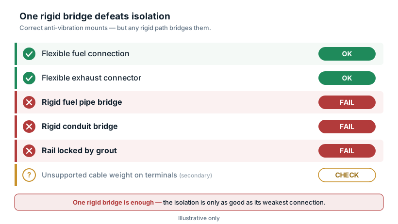
Perfect anti-vibration mounts and one rigid pipe give you an unisolated set. It is as-built drift you can only feel under load.
Accept it only when every service into the set flexes, the mounts are free and correctly loaded, and the cables carry their own weight. On the drawing, the mounts and flexible connectors match the approved submittal, and the cable support is drawn independent of the terminals. On site, look for the bridge: mounts locked by grout, a rigid pipe or conduit running straight to the structure, or output cables hung on the alternator terminals, whose weight loosens them over time. Prove it under load — vibration and structure-borne transmission within the maker's allowable vibration and the approved AVM criteria, a check against a limit, not an impression. It survives handover because the mounts look perfect, and one rigid pipe only speaks when the set runs.
Fuel delivery — field faults behind a good tank
A compliant tank proves nothing about the line that feeds the engine. This is drift that stays hidden until the set sits idle.
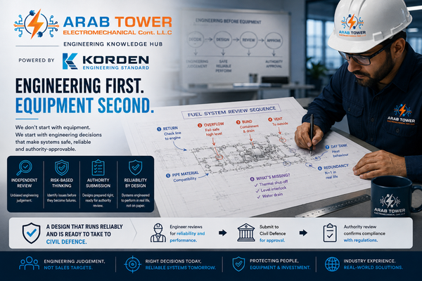
Accept it only after the fuel path holds its prime and feeds cleanly on a real run — and matches the approved design, not merely the pipe dimensions. On the drawing, the material, fill, vent, overflow, supports and flexes follow the approved fuel-system design, the OEM requirements and the authority submission; a site substitution is not acceptable just because the dimensions fit. On site, the suction side is where it goes wrong: an unsealed joint draws air, and the set loses prime between runs. Prove it by leaving the set, then starting it cold on its own fuel under load — prime-hold plus a loaded run exposes the common suction-side faults, but it does not replace the full approved fuel-system commissioning. It survives handover because it was primed by hand on the day.
Tank, bund and Civil-Defence approval → Fuel System.
Earthing and terminations — what only the right test finds
This is the one family where looking proves nothing — it is exactly the drift the as-proven gate exists to catch.
Accept it only when the neutral-earth bonding and the transfer-switch neutral arrangement match the approved system earthing philosophy, no unintended parallel neutral-earth path has been introduced, and the terminations are sealed. On the drawing, where the neutral is bonded — and whether the transfer switch switches it — depends on whether the set is a separately derived source and on the source earthing and protection scheme; there is no fixed "one bond, one place" rule, and the CTs must show the right orientation and circuit. On site, the classic error is a second neutral-earth bond added in the panel, making a parallel path. Prove each fault with its own test — electrode resistance for the electrode, continuity for the bonding conductors, a neutral-earth path check for a second bond, and polarity or secondary-injection for the CTs — because one test does not prove another. It survives handover because a duplicated bond or a reversed CT passes a casual continuity check.
The earthing philosophy itself → Earthing & Protection.
The state it's left in — will it start on its own?
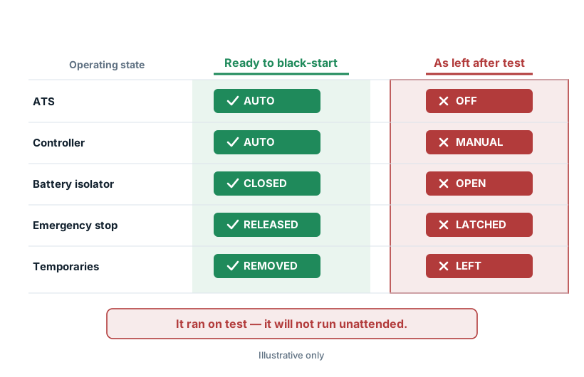
It ran on test because a person was standing there; on the day, no one will be. This is pure as-operated drift — the set proven, then quietly un-set.
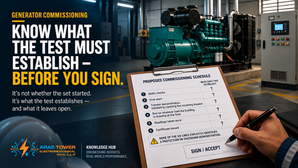
A set that runs when you press start is not one that will start, transfer and hold the load automatically. Accept it only after a controlled automatic mains-failure test proves the full sequence completes without manual intervention. On the drawing, the auto-start and transfer logic must take the load on loss of mains with no manual step, and no temporary supplies are designed in. On site, the whole risk is a switch left wrong: AUTO not OFF or MANUAL, isolator closed not open, e-stop released not latched, every temporary removed. Prove it with a planned, authorised, risk-assessed and witnessed mains-failure simulation in which the controller detects the loss, starts, transfers and holds — "unattended" means the sequence completes with no manual step, not that the test is left unsupervised — and prove the battery under a real crank. It survives handover because it ran when a person pressed start; the automatic sequence was never proved end to end.
In the composite case this was the gap that mattered most: months in, the ATS had been left out of AUTO — introduced after handover, not present at commissioning.
No-start diagnosis → Why Generators Fail to Start.
So who was supposed to catch this?
Almost every failure above is really a handoff no one owned — each engineer assuming the last had it covered. The five states already name the owners; the discipline is only to ask, at your own gate, one question: if this drifts, would I catch it, or would the next person inherit it?
| Gate | What closes it |
|---|---|
| As-designed | Each assumption made checkable — the check, the tolerance, and a load test written into the plan |
| As-submitted | Rejecting the submittal that hides a small free area, a tight exhaust route, a second bond or a missing flex |
| As-built | Confirming, item by item, that what is fitted is what was drawn — and that nothing temporary is left |
| As-proven | Proving it on load — cooling, back-pressure, earthing, and the automatic sequence — all recorded |
| As-operated | Keeping it in the state it was proven in, and re-verifying after any later work |
None of these gates is hard. They are missed because each belongs to someone else's stage — and the outage does not care whose.
What would convince you the set is actually ready?
Not the handover certificate. You are not collecting paperwork; you are looking for proof that the drift was closed and the set was made to work when it mattered. Six things would convince a careful engineer:
- the as-built checked against the as-designed, and signed off;
- a load-test record — the load, the duration, the temperatures, how it took the block loads;
- the measured exhaust back-pressure, within the engine's limit;
- earthing, continuity and CT results, each the right test for its fault;
- a witnessed automatic mains-failure test in which the set started, transferred and held, battery proven under crank;
- a defects list that is closed, not open.
If those exist, the set is proven. If they don't, it isn't — however good it looked on the day. Inherit a set with none of them and you have not inherited a working generator; you have inherited an untested one.
What the UAE adds — as-operated drift
The failures above are built-in, present at handover. The UAE adds a second kind: a set that was proven slips out of that state afterwards.
| Reality | How it creates installation drift |
|---|---|
| High ambient and desert dust | Dust fouls cores, louvres and filters, so the as-built cooling slowly falls below the as-designed — the margin the design assumed erodes, and shows only on a hot day. |
| Coastal humidity and corrosion | Enclosures, exhaust terminations, glands and earth connections corrode, turning a sound as-built electrical and exhaust install into an unsound as-operated one. |
| Shared basement ventilation | The cooling air shares routes with car-park and smoke systems; a later air-balancing change quietly starves or short-circuits it, so the as-operated air path drifts from the as-built. |
| Room and services changed after handover | Louvres blocked, access lost, later pipework across the removal path, Civil-Defence arrangements altered — each drifts the set away from the state it was proven in (Civil-Defence changes → the Fuel System guide). |
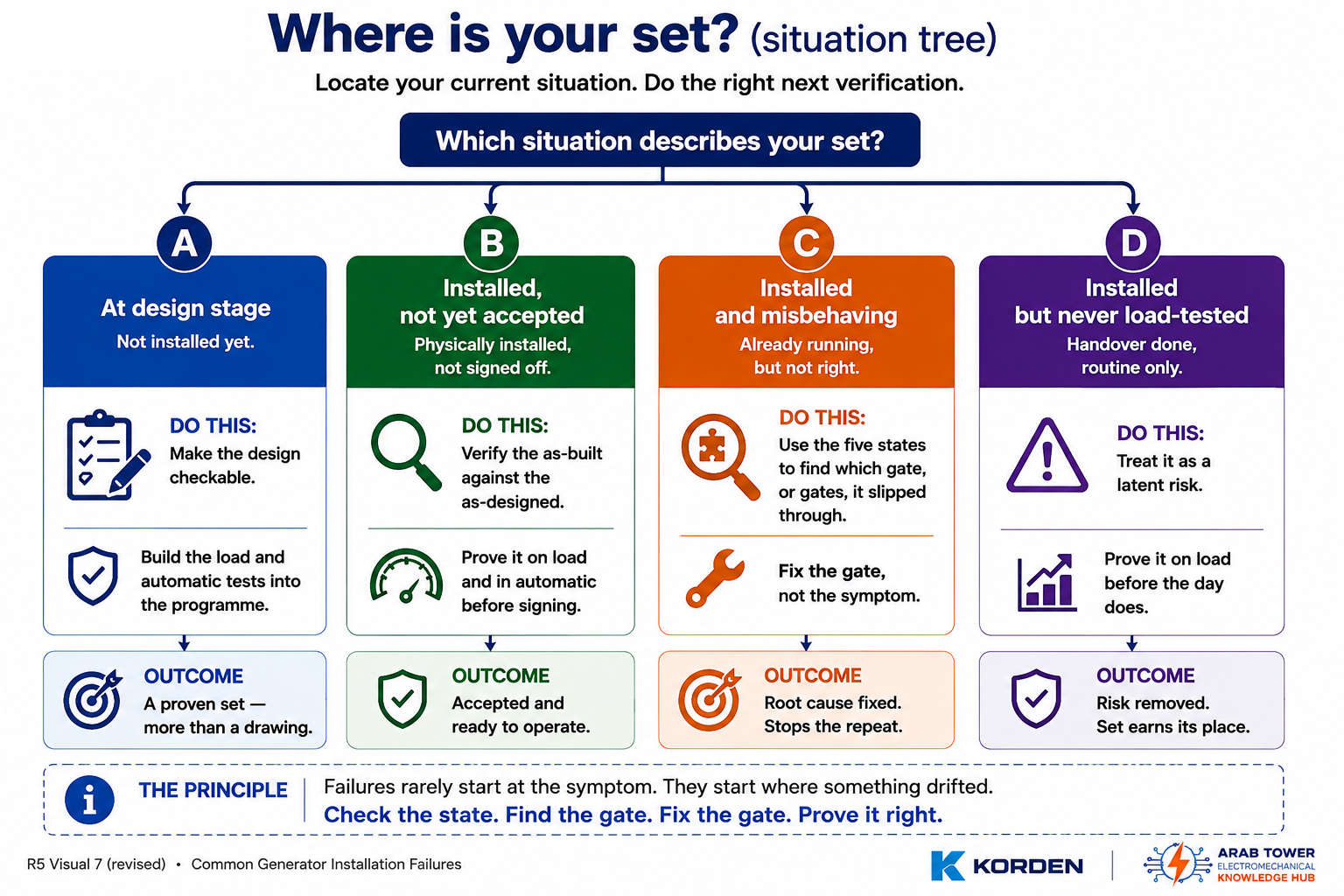
Where are you standing today?
The right next move depends on it.
- At design stage — make the design checkable and build the load and automatic tests into the programme now; the cheapest place to close every gap is before it is built.
- Installed, not yet accepted — don't sign on a cool-day, no-load test. Verify the as-built against the as-designed and prove it — on load and in automatic — first.
- Installed and misbehaving — use the five states to find which gate, or gates, it slipped through, and fix those, not the symptom.
- Installed but never load-tested — you have a latent risk, not a healthy set. Prove it before the day proves it for you.
A generator earns its keep on one day you cannot predict, and on that day the drawing will not be in the room — only what was built and what was proven. In the composite case, the built-in gaps would have shown under a planned combination of loaded generator testing and an integrated automatic mains-failure test; the ATS left out of AUTO was a later drift a re-verification would have caught.
A correct design is where reliability begins; proving the installation is where it is earned. The outage never invents a new fault — it only introduces you to the ones nobody proved.
— Want a second set of eyes? Send us the installation drawings and commissioning records, or the site → and we will verify the installation against its own design and prove it on load.
Engineering references — reference families to confirm for the specific project (edition and applicability vary): generating-set performance and installation (ISO 8528); emergency/standby power and stationary engines (NFPA 110, NFPA 37); earthing and wiring (IEC 60364, UAE Wiring Regulations 2020); fuel and fire safety (UAE Fire and Life Safety Code / Civil Defence); and the engine, alternator and controller manufacturers' installation and commissioning manuals — which govern the set-specific limits used above (cooling data, allowable back-pressure, allowable vibration, bonding arrangement and the start/transfer sequence).
Related guides: Generator Room Design · Generator Fuel System · Generator Earthing & Protection · Generator Sizing · Generator Commissioning · Load-Bank Testing · Why Generators Fail to Start.