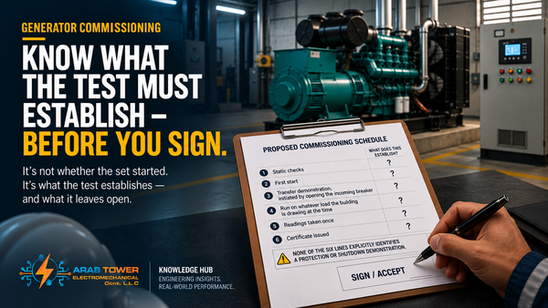
Generator Synchronization Explained: How to Parallel Generators Correctly
Two identical, healthy generators. Voltage matches, frequency matches — and closing the breaker at the wrong instant can still wreck one of them. Here is how to synchronise and parallel generators correctly.

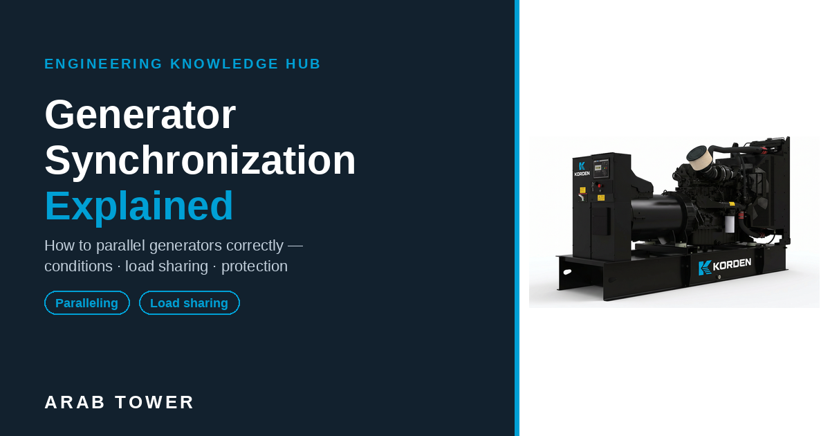
Two generators. Same make, same rating, both in perfect health. Put a meter across each and the voltage reads the same. Put a frequency counter on each and both show 50.0 Hz. By every gauge on the panel, they are identical and ready to join.
Close the breaker to connect them, and in a quarter of a second you can wreck one of them.
Not with a short circuit. Not with an overload. The voltage matched. The frequency matched. And it was still the wrong instant to connect.
That is the part that catches good engineers out. Matching the two numbers everyone watches — voltage and frequency — is not the same thing as being safe to close. Something the panel gauges barely show decides whether the two machines slide together quietly or slam together hard enough to crack a shaft.
So what is the panel not telling you — and how can two "matched" generators still destroy each other?
Because at the instant the breaker closes, the two machines lock together and pull hard into step. Do it lined up and they settle. Do it out of line and they snap — and the snap goes through the iron.
Synchronising is not matching a number. It is the craft of making two machines join softly. This guide walks through how, in order.
What will this guide settle — and what will it leave to other guides?
It settles enough to parallel a normal multi-set installation correctly and to diagnose the faults that stop it: why generators are synchronised and where it is done · what synchronising really is · the four conditions at closure · what happens when you close aligned versus misaligned · the system and its components · the synchronising methods and operating modes, and when each applies · sharing load once paralleled (kW and kVAR) · why healthy sets still refuse to share · reverse power and the protection that keeps paralleling safe · dead-bus and black-start sequencing · a note on paralleling with the utility.
It deliberately does not cover here (kept short and linked, so this stays one clear path): generator sizing and selection, full protection-relay settings, deep load-sharing theory, the complete utility-interconnection process, enclosure and room design, and the full commissioning procedure. Each has its own guide.
We will bring one real installation online as we go, so each decision lands on something you can picture.
Our worked scenario: a UAE building with two standby generators on a common paralleling board — later a third, for N+1 — feeding a mixed load of chillers, a small server room on a UPS, lifts, and a fire pump. Standby duty: the utility is there, and the generators back up the building on a power cut. Ordinary on purpose — you will recognise your own project in it.
Why parallel generators at all — what problem does synchronising solve?
Before the how, settle the why. Paralleling switchgear and synchronising controls cost money, so it is worth being clear about what they buy you.
Every reason below is an engineering outcome, not a slogan:
- Increased capacity. Combine sets to serve a load no single available set can carry, and add power in blocks as the load grows.
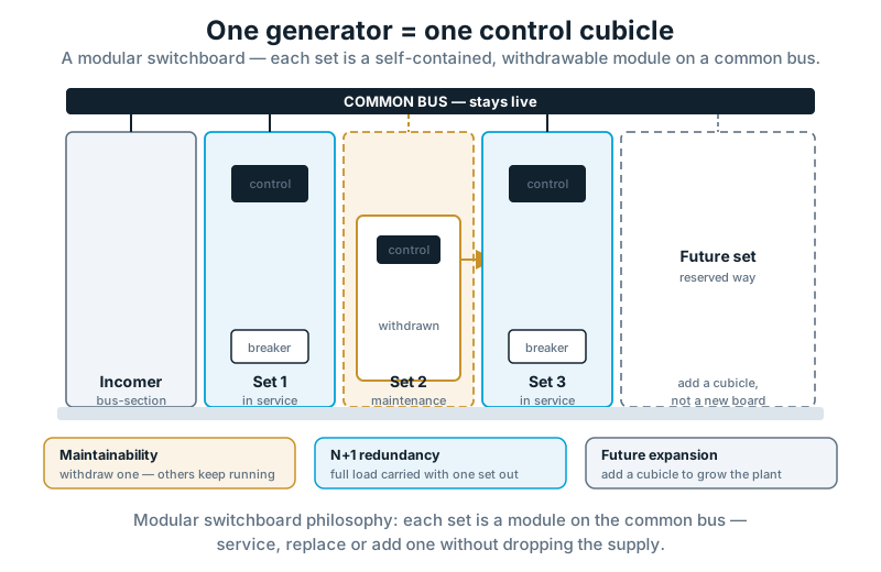
- Redundancy (N+1). Size the plant so the full load is carried with one set out of service. The spare set is only real if the sets can parallel and share.
- Maintenance without shutdown. Take one set offline for service while the others hold the load. For a facility that cannot go dark, this is often the whole reason the bus exists.
- Fuel optimisation. Run fewer sets nearer their efficient load band instead of several sets lightly loaded. (Running a set too lightly brings its own problems — see the sizing guide.)
- Peak-demand management. Bring sets onto the bus to meet a peak, then drop them off as demand falls.
- Future expansion. A paralleling bus lets capacity grow by adding a set, rather than replacing one that has become too small.
- Reliability. Several smaller sets sharing the load mean a single failure is a fraction of the plant, not all of it.
- Business continuity. For sites where an outage has consequences well beyond inconvenience, paralleling is how supply is held up through both faults and maintenance.
For our building, two reasons decide the architecture: N+1 redundancy (the load must be carried with one set down) and maintenance without shutdown. That is why it has a paralleling board and not one large set.
Paralleling is an availability decision before it is an electrical one. If none of the reasons above applies, a single set may be the right answer — synchronising is a tool, not a default.
Several sets, or one large one?
This question comes up on almost every project: why buy three 800 kVA sets and a paralleling board when one 2500 kVA set would do the same kW for less switchgear? Sometimes the single set is right. Often it is not, and here is the engineering behind that:
- Redundancy. One large set is a single point of failure — when it is down, everything is down. Three smaller sets sharing means one failure costs a third of the plant, not all of it.
- Maintenance. You can service one set in a multi-set plant while the others carry the load. A single set has to be stopped to be maintained — and with it, the supply.
- Logistics. Smaller sets are easier to deliver, crane, and site, and their spares and service are easier to source. A very large frame can be a transport and rigging project on its own.
- Scalability. A bus lets you add capacity a set at a time as the building grows. A single large set is a fixed bet made on day one.
- Lifecycle cost. Running fewer sets in their efficient band and resting the rest can beat one large set held at low load for years — and staged replacement spreads the capital.
- Operational flexibility. The plant can match running capacity to demand — one set overnight, three at peak — instead of running one large machine lightly most of the time.
The trade is more switchgear, controls and commissioning — which is exactly the competence this guide is about. The single large set wins where redundancy is not required and the load is steady; the paralleled plant wins almost everywhere availability matters.
Where is generator synchronisation actually used?
You find paralleled generators wherever losing supply is expensive, and the mix of loads tells you what will dominate the scheme:
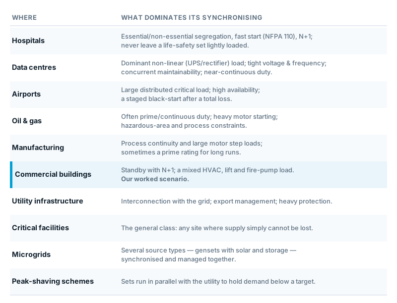
Find your row and you already know which later sections matter most. Our path is the commercial building; step across when your project sits elsewhere (see the decision tree near the end).
What actually has to match before you close?
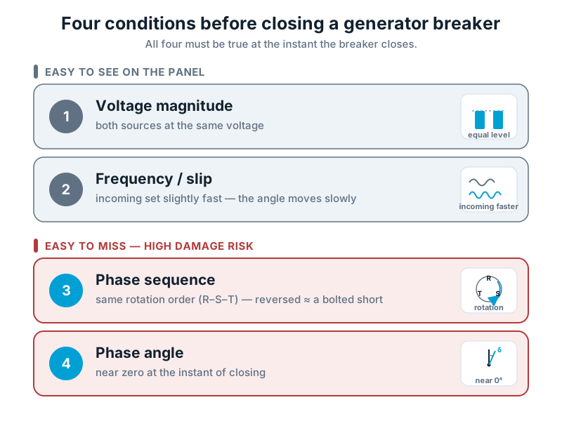
Here is the heart of the opening paradox. Voltage and frequency are two of four conditions, and they are the two the panel shows you clearly. The other two are the ones that do the damage.
To close cleanly, the incoming machine and the live bus must agree on all four:
Voltage magnitude. Both at the same voltage. A difference drives a reactive current surge at the instant of closing.
Frequency (slip). Almost the same speed. You do not aim for exactly equal frequency — you bring the incoming set up a touch faster than the bus, so at the instant of closing it is pushing to take up load rather than being dragged as a motor. A small, controlled slip lets the angle drift slowly toward zero, which is what a good close is made of. Too much slip, and the angle races through the safe window before the breaker can catch it.
Phase sequence. The three phases in the same rotational order. Reversed sequence is roughly a 120° error on two phases — close on it and it is effectively a bolted short circuit. This is proven once, at installation.
Phase angle. The rotating angle between the two machines near zero at the instant of closing. Close at a large angle and you get fault-level current and a violent torque step through the shaft. This is the live decision at every close.
Now the point the opening turned on: voltage and frequency sit on the front of the panel. The two that wreck machines — phase sequence and phase angle — are the two the panel barely shows. That is why everything the operator was watching looked right.
What really happens at the instant you close?
This is why the closure instant matters so much, and it is worth slowing down for.
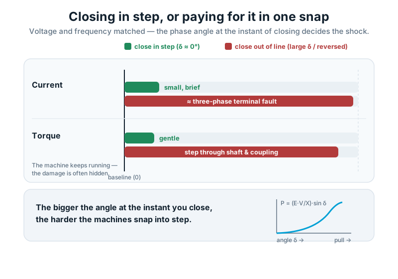
Once two machines are paralleled, they are locked together electromagnetically and held in step by a synchronising force. In plain terms: the further out of line the two rotors are, the harder that force pulls them together.
Written down, the power crossing the closing gap is P = (E·V/X)·sin δ, where δ is the angle between the two machines. You do not need the equation to feel the point — the bigger the angle at the instant you close, the harder the pull. The force behaves like a stiff spring between the two rotors.
Close with the angle near zero and the spring engages with almost no tension. The machines slide into step and settle.
Close at a large angle, or on reversed phase sequence, and the spring is already stretched hard at the instant of contact. It releases that energy through the shaft, the coupling and the windings in one snap. The current looks like a three-phase terminal fault. The torque can crack a coupling or a crankshaft.
The dangerous part is what you cannot see. A bad close does not always announce itself. The set may keep running afterwards, and the damage hides in the shaft, the coupling and the winding insulation — cumulative, invisible, adding up over months until something lets go on an ordinary day.
Engineering observation — a bad synchronising close is not a nuisance event; it is a fault-level mechanical and electrical shock. Treat every close as the moment the machine is most at risk, because it is.
What we see on site — cracked couplings and spun crank keys that trace back not to one dramatic failure but to a run of slightly-out closes nobody logged. The machine that "sometimes trips on close" is telling you something.
A short history: how did we get from lamps to intelligent controllers?
It helps to know how synchronising has been done, because you still meet every generation of it on site.
- Synchronising lamps. The oldest method: lamps connected across the open breaker that go dark (or bright) as the two supplies drift in and out of phase. Simple and cheap — but a lamp goes dark at about half voltage, so "dark" is not always "in phase."
- The synchroscope. A dial with a pointer that rotates to show the angle and its direction — slow rotation toward the "12 o'clock" mark means you are nearly there. It made manual synchronising far more precise than lamps, and it is still the mental picture behind every modern display.
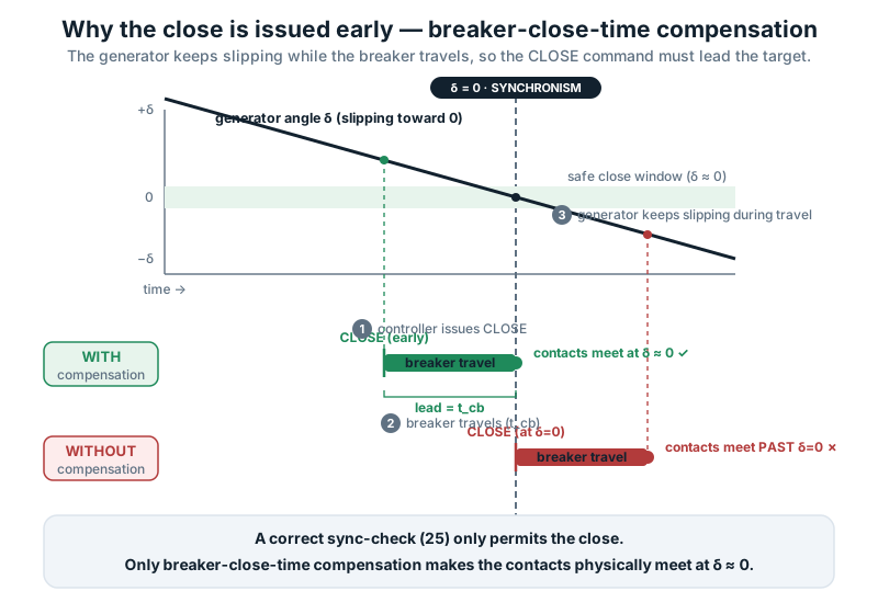
- Digital / static synchronisers. Electronic relays that measure voltage, frequency and angle and issue the close automatically, advanced for the breaker's travel time. They took the human reaction time out of the close.
- Modern intelligent controllers (for example DSE, ComAp, DEIF). Today's genset controllers combine the synchroniser, the load-share functions, the sequencing and the protection interface in one module, with an HMI that shows the synchroscope view and the load-share bars, and links up to SCADA or the building system.
The physics has not changed since the lamps. What changed is that the match, the close timing and the load sharing are now measured and managed automatically — and understanding the old methods is still the fastest way to understand what the controller is doing for you.
What is actually in a synchronising system?
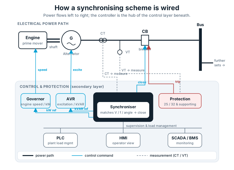
Before you specify one or troubleshoot one, it helps to know what the parts are and what each one does. Follow the signal path from the engine to the bus and up to the supervision:
- Generator (set) — the packaged source: the machine you are bringing onto the bus.
- Engine (prime mover) — supplies the mechanical power; its speed sets the frequency. Controlled by the governor.
- Alternator — converts mechanical power to electrical; its excitation sets the voltage. Controlled by the AVR.
- Governor — controls engine speed and fuel, so it sets kW and frequency. The basis of real-power sharing.
- AVR (automatic voltage regulator) — controls excitation, so it sets voltage and kVAR. The basis of reactive-power sharing.
- Synchroniser — matches voltage, frequency and phase angle, and issues the close command at the right instant. On a real close it issues that command early, to allow for the breaker's travel time.
- Controller (genset control module) — runs the set: it hosts the synchroniser and the load-share functions and sequences start, stop, dead-bus closing and load management.
- Circuit breaker (ACB or MCCB) — makes and breaks the connection to the bus. Its closing time is a number the synchroniser must know and compensate for.
- CTs (current transformers) — measure current for metering, load sharing and protection. Their polarity matters — get it wrong and reactive sharing and reverse-power sensing go wrong with it (more in the faults section).
- PTs / VTs (voltage transformers) — provide the voltage references the synchroniser and the protection compare across the breaker.
- Protection relays — the device set that keeps paralleling safe (covered below).
- PLC (where fitted) — plant-level logic on larger schemes: load-dependent start/stop, set priority, load shedding.
- HMI — the operator's window: the synchroscope view, load-share bars, alarms and mode selection.
- SCADA / BMS integration — plant-wide monitoring, trends, alarms and remote control.
On our board, that is the whole picture: two engines and alternators, each with its governor and AVR, each with a controller hosting the synchroniser, feeding a common bus through breakers, with CTs and PTs for metering and protection, and an HMI the operator watches.
Engineering observation — most people can name the generator and the breaker and stop there. The parts that decide whether paralleling works are the governor, the AVR, the CTs and the controller — and they are exactly the parts a single-line diagram tends to hide.
Manual, automatic — and which mode for which job?
There is more than one way to synchronise, and more than one way to run the bus once you have. Pick the method to suit the plant and the moment.
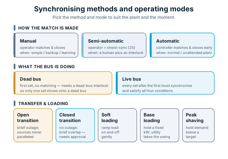
How the match is made. Manual — the operator matches on a synchroscope or lamps and closes by hand; fine for simple, infrequent or backup operation, and how the fundamentals are learned. Semi-automatic (permissive) — the operator initiates, but a check-sync relay (ANSI 25) blocks the close unless voltage, frequency and angle are inside a window. Automatic — the controller measures the match and issues the close itself, advanced for the breaker's closing time; normal operation for multi-set and unattended plant.
Compare — Manual vs Automatic synchronisation
Manual: operator matches and closes · slow · depends on skill and attention · good for backup and learning · a lamp can read "dark" while an angle remains.
Automatic: controller matches and closes · fast and repeatable · compensates breaker-close time · standard for multi-set/unattended plant · still needs correct settings and testing.
The mechanism worth understanding, in plain words: the close is issued early so that, after the breaker has travelled, the contacts meet at zero angle. On a slow breaker a correct permissive is not enough on its own — if the closing time is not compensated, the angle overshoots the window while the breaker is still moving. A happy sync-check relay is not proof of a good close; the breaker's own timing is part of the sum.
What the bus is doing. The first set energises a dead bus — nothing to match, so no synchronising, but a dead-bus interlock must ensure only one set takes it. Every set after that synchronises onto the live bus.
Compare — Dead bus vs Live bus
Dead bus: bus de-energised · first set closes with no matching · needs a dead-bus interlock so only one set closes · the black-start case.
Live bus: bus already energised · every incoming set must satisfy all four conditions and close gently · the normal case.
How the source is transferred and load is managed. Open transition (break-before-make) is a brief, deliberate interruption — the two sources are never connected, so no synchronising is required. Closed transition (make-before-break) is a brief synchronised overlap so the load never sees a break — it requires synchronising, and with the utility, the authority's approval. Soft loading ramps load on and off a set gently. Base loading holds a set at a fixed kW while another source takes the swing. Peak shaving runs sets in parallel with the utility to hold demand below a target.
Compare — Open vs Closed transition
Open (break-before-make): momentary outage · sources never paralleled · no synchronising, no utility approval needed · simplest and safest to permit.
Closed (make-before-break): no outage · brief synchronised overlap · needs synchronising and, with the utility, formal approval and interconnection protection.
On our building, the sets auto-synchronise onto a live bus. If the board must also parallel briefly with the incoming supply on a return-to-mains, that is a closed transition — which brings in the utility layer covered further down.
Match the method to the plant: manual for simple or backup, permissive where you want an interlock, automatic for normal multi-set running. And decide open versus closed transition early — it changes the protection and approvals you need.
The sets are paralleled — so why won't they share the load?
Getting two sets onto the same bus is only half the job. Now they have to share, and this is where most real paralleling problems live.
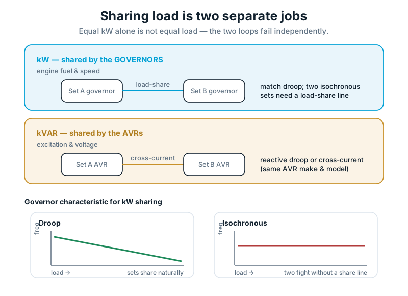
The trick is to stop thinking of "load" as one thing. It is two: real power (kW) and reactive power (kVAR), and each is handled by a different controller.
Compare — Governor vs AVR
Governor: controls engine fuel and speed → sets kW and frequency → the basis of real-power sharing.
AVR: controls alternator excitation → sets voltage and kVAR → the basis of reactive-power sharing.
These are two independent control loops, and they fail independently. You can have perfect kW sharing and badly split kVAR at the same time. kW is a governor problem; kVAR is an AVR problem. Confuse the two and you will chase the fault forever.
For kW sharing, there are two philosophies:
Compare — Droop vs Isochronous
Droop: speed falls slightly as load rises (typically 3–5%) · simple and stable · two droop sets share naturally · frequency sags a little with load.
Isochronous: frequency held dead flat regardless of load · perfect for one set alone · two uncoordinated isochronous sets fight for control · needs a load-share line or one set as the reference.
For kVAR sharing, the AVRs need either reactive (quadrature) droop — voltage falls slightly with reactive load, the mirror of governor droop — or cross-current compensation, where the AVRs are wired together to balance reactive load between them. Cross-current schemes generally want the same AVR make and model on each set to behave.
On our building, we bring the second set up, match it, close, and then load it: raise its governor set-point until it takes its share of kW, and confirm its AVR is taking its share of kVAR. Only when both are shared is the set truly carrying its half.
Real power and reactive power are shared by different controllers. Verify both — equal kW alone is not equal load.
What do the classic sharing faults actually look like?
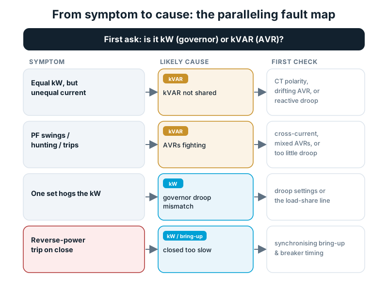
This is the section to bookmark, because these are the faults that put a commissioning engineer on site. Read them as symptom → cause → what to check:
Both sets show equal kW, but one carries much higher current. Current follows kVA, not kW — so this is kVAR not being shared. Check the current-transformer wiring (a reversed CT is the classic cause), a drifting or failing AVR, or mismatched reactive droop. Everything looks right on the kW meters while the reactive load piles onto one machine.
Power factor swings and the sets hunt, sometimes to a trip. The AVRs are fighting for the reactive load — incompatible cross-current settings, mixed AVR types, or too little reactive droop. This "PF hunting" is a common cause of nuisance trips on a freshly commissioned bus.
One set hogs the kW while the other loafs. The governor droop settings differ, or one is in droop and one in isochronous without a load-share line. The flatter characteristic takes the load.
The incoming set trips on reverse power just after closing. It was closed too slow — not brought up to push into load — so at the instant of closing it was being dragged as a motor instead of taking its share.
What we see on site — two "identical" sets that will not share, and the fault is almost never the machines. It is a wiring polarity, a droop setting, or two AVRs that were never meant to work together. Identical hardware does not guarantee identical behaviour.
What we see on site — a bus that shares perfectly at unity power factor and falls apart the moment a real reactive load arrives. Reactive sharing has to be proven under reactive load, not at no load.
Split the fault before you chase it: is it kW (a governor/droop problem) or kVAR (an AVR/wiring problem)? Naming which loop is wrong is most of the diagnosis.
What protection makes paralleling safe?
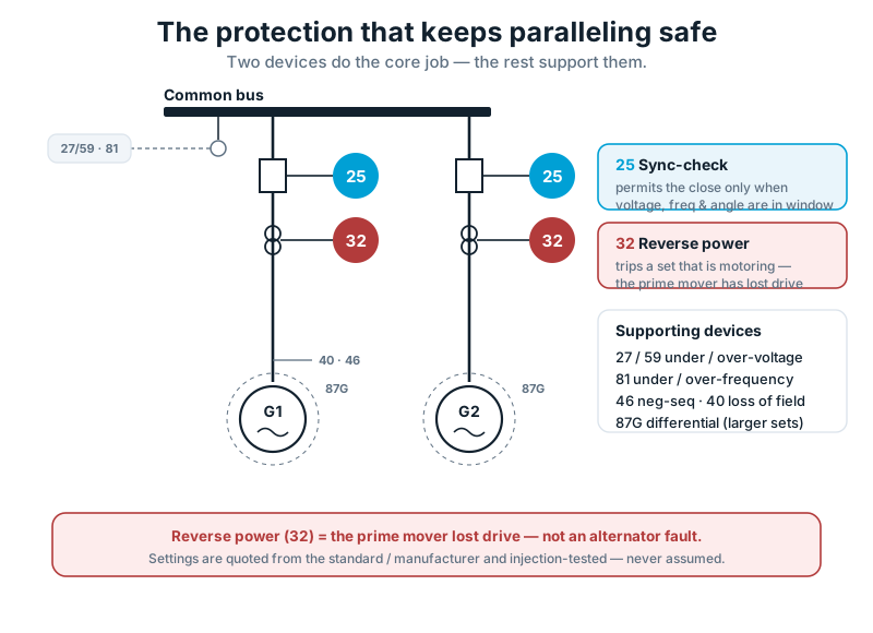
Paralleling adds failure modes a single set never has, so it adds protection. Two devices are the core of it, and a handful more support them.
- Sync-check (ANSI 25) guards the closure. It blocks the breaker from closing unless voltage, frequency and angle are inside the window — the interlock behind semi-automatic and automatic synchronising.
- Reverse power (ANSI 32) guards against motoring. If a set's prime mover loses drive while still paralleled, the machine is dragged by the others as a motor, drawing power in instead of producing it. Device 32 detects that reverse flow and trips the set off the bus.
That second one is widely misdiagnosed, so state it plainly: reverse power is not an alternator fault. It is the engine losing power while still connected. A dropped fuel rack, an air-starved engine, a fuel-supply problem — the alternator is fine; it is being spun by the bus. Blaming the alternator sends the callout to the wrong place.
On our building, each set has 25 guarding its close and 32 guarding against motoring, with under/over-voltage and frequency supervision on the bus. The heavier devices (differential, loss of field) come in as the sets get larger.
Common review finding — protection that exists in the relay but was never injection-tested against the scheme. A setting typed into a relay is a document, not a proven function, until it is tested.
What changes when you parallel with the utility?
Everything so far has assumed the generators parallel with each other on an island bus. Paralleling with the utility is a different problem, and a bigger one.
Compare — Island mode vs Utility parallel
Island mode: generators supply the site alone · they set the frequency and voltage · protection guards the sets and the bus · no external permission.
Utility parallel: generators run alongside the grid · the grid sets frequency and voltage · adds interconnection protection and loss-of-mains detection · requires the authority's approval.
Two things get added when you go to utility parallel.
First, interconnection protection: the scheme must guarantee the generators cannot feed the network in a way the utility has not sanctioned, and must disconnect cleanly if the utility supply fails. That failure case is loss of mains (anti-islanding), detected by methods such as rate-of-change-of-frequency (ROCOF) or vector shift, so a set is never left energising a section everyone believes is dead. You also decide whether the scheme exports to the grid or holds at no export.
Second, the regulatory layer. Paralleling with the utility needs the network operator's approval. In the UAE that is Etihad Water & Electricity in the Northern Emirates, including Ajman, or DEWA in Dubai, depending on where the site sits. They set the interconnection requirements and the protection they will accept.
The honest caution: the exact interconnection settings and approval requirements must come from the current authority guidelines for your site — not from a guide, and not from memory. They change and they differ by operator. What this guide can tell you is that utility paralleling needs interconnection protection, loss-of-mains detection and formal approval; the specific figures belong to the operator's live documents and to the utility-paralleling guide in this series.
Island-parallel or utility-parallel is the first fork in any paralleling scheme, and it changes the protection and the permissions, not only the wiring.
Which set starts a dead bus — and in what order?
One case sits outside everything above: the total blackout, when the bus is dead and there is nothing to synchronise to.
On a mains failure the sets are called to start. The first set to reach voltage and speed closes onto the dead bus — no matching to do, because nothing is energised to match. It simply energises the bus. This is why the dead-bus interlock matters: only one set may take the dead bus, or two unsynchronised machines close together.
Once the bus is live, every following set synchronises onto it in the normal way — matches, closes gently, loads up to share. When the utility returns, the scheme transfers back, by open transition (a brief break) or closed transition (a synchronised overlap).
So the first close in a black-start is the one close in the whole sequence that needs no synchronising — and every close after it needs all four conditions again.
Black-start is one dead-bus close followed by ordinary live-bus synchronising. Get the interlock and the sequence right and the plant comes up in order.
Which paralleling path is your project?
Our worked scenario is one path — a two-set standby building. Other projects weight the same steps differently. Find yours:
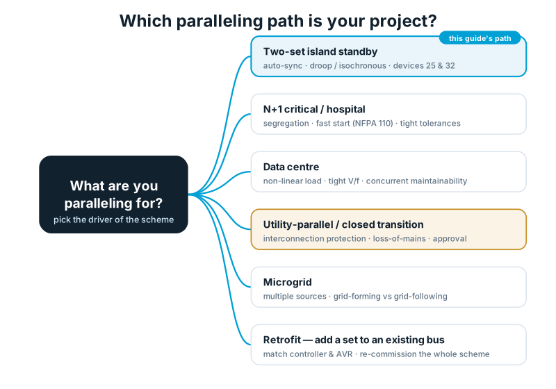
Each has its own guide. This one takes the two-set standby path all the way; step across when your project sits in another row.
Where does generator synchronising usually go wrong?
A quick self-check against the ones we see most:
- "Voltage and frequency match, so it's ready." The two conditions that damage machines — phase sequence and phase angle — barely show on the panel. Fix: prove all four.
- Trusting the permissive on a slow breaker. A happy sync-check relay still overshoots if breaker-close time is not compensated. Fix: compensate for the breaker.
- Assuming identical sets will share. Reversed CT wiring, mismatched droop, or fighting AVRs stop them. Fix: split kW from kVAR and verify each.
- Blaming the alternator for reverse power. It is the prime mover losing drive. Fix: look at the engine and fuel first.
- Under-scoping paralleling as "wiring gensets to one bus." It is a system — switchgear, controllers, protection, load-share scheme, transition logic, and, for utility parallel, formal approval. Fix: specify the system.
- Setting protection but never testing it. A setting in a relay is not a proven function until it is injection-tested. Fix: commission it.
What does it take to commission a paralleling scheme?
The number on the drawing is only the intention. A paralleling scheme is proven on site — and a correct bring-up follows a fixed order, from a cold engine to a shared, protected bus:
- Engine start — the set is called and cranks.
- Warm-up — the engine runs up and stabilises before it is asked to take load.
- Voltage build-up — the AVR brings the alternator to rated voltage.
- Frequency stabilisation — the governor settles the set at rated speed.
- Synchronisation — the synchroniser matches voltage, frequency and angle to the live bus (or, for the first set, prepares to close a dead bus).
- Breaker closure — the close is issued, compensated for breaker travel, so the contacts meet at zero angle.
- Soft loading — load is ramped onto the set gently rather than in a step.
- Load sharing — kW and kVAR are balanced against the other sets, on real load.
- Normal operation — the set runs in step, sharing its share, under live protection.
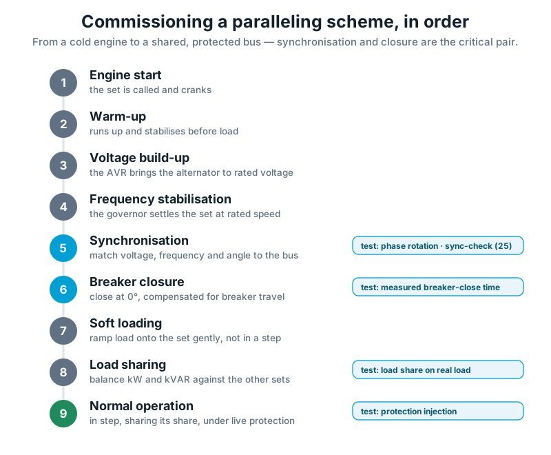
The tests that prove each stage are the usual ones: phase rotation before any first close, the sync-check permit-and-block, the measured breaker-closing time, load sharing verified on real load, and the protection injection-tested against the scheme rather than assumed from the settings sheet.
Do that and the scheme does on the worst night what it did on the commissioning day. Skip it and the faults in this guide are the ones you meet later, under load, in the dark.
Where is generator synchronisation heading?
The four conditions will not change — but what sits on the bus is changing fast, and it is worth knowing where the field is going:
- Hybrid systems put diesel sets alongside other sources, running them together to cut fuel and run-hours.
- Battery energy storage (BESS) absorbs steps and short peaks, so the engines see a smoother load — and can take over instantly while a set starts.
- Renewable integration (solar, and sometimes wind) adds sources whose output moves with the weather, which the control scheme has to manage against the gensets.
- Grid-forming inverters let batteries and converters set voltage and frequency the way a synchronous machine does — changing what "the reference" on a bus even means.
- AI-assisted optimisation tunes which sets run, when, and at what load, from live demand and forecast rather than fixed rules.
- Intelligent microgrids tie all of the above together, synchronising and arbitrating between gensets, storage and renewables as one managed system.
None of this removes the fundamentals in this guide — matching, closing gently, sharing through two control loops, and protecting the plant. It adds new sources that must play by the same rules. (Microgrid and hybrid design is its own subject; this guide stays with generator-to-generator and generator-to-utility paralleling.)
Which standards sit behind these decisions?
ISO 8528-1 (generating-set ratings and load acceptance), ISO 8528-5 (transient performance), IEC 60034-1 (alternator rating and temperature), the ANSI/IEEE C37.2 device numbers used throughout (25 sync-check, 32 reverse power, 27/59, 81, 46, 40, 87G), IEEE C37.102 (generator protection application), IEEE 1547 (interconnection of distributed resources, as an international reference), and NFPA 110 (emergency and standby power systems).
For utility paralleling in the UAE, the interconnection and approval requirements come from Etihad Water & Electricity or DEWA for the specific site, and must be read from their current guidelines. Each standard sets a limit or a method — none of them makes the decision for you. That is still the engineer's job.
A few questions we are asked often
Why do generators have to be in phase before connecting? Because at the instant you close, the machines lock into step. Out of phase, that alignment happens as a violent snap — fault-level current and a torque step through the shaft. In phase, they slide together gently.
Why won't my two identical generators share load? Sharing is two separate jobs: kW by the governors, kVAR by the AVRs. Identical machines still won't share if a CT is wired the wrong way round, the governor droop settings differ, or the AVRs are fighting. The hardware is rarely the fault.
What causes a reverse-power trip? The prime mover losing drive while the set is still paralleled — the machine is dragged as a motor. Device 32 trips it. Look at the engine and its fuel, not the alternator.
Do modern generators still use synchronising lamps? Lamps and synchroscopes are still taught and used as a backup, but modern land gensets synchronise automatically through their controllers. A lamp can mislead — it goes dark at about half voltage, so "dark" is not always "ready."
Do I need approval to parallel with the utility in the UAE? Yes. Paralleling with the utility — even a brief closed transition — needs interconnection protection and approval from Etihad Water & Electricity or DEWA for your site. The specific requirements come from their current guidelines.
Want a second set of eyes on your paralleling scheme?
One last thing worth saying plainly. A paralleling scheme is only as good as its weakest connection — a CT the wrong way round, a droop setting that does not match, a breaker whose closing time nobody measured. Each is invisible on the drawing and obvious under load. That is exactly why a second look is worth having.
So if you want a paralleling scheme checked — a new design, or one that will not close, will not share, or keeps tripping — send us three things:
- the single-line diagram,
- the protection schedule, and
- the controller / load-share configuration.
We will review it, or commission it, and tell you what we find and why. It is the same method you have just read — and the review stands on its own, whether or not you buy the switchgear from us. Arab Tower designs, supplies, installs, tests and commissions paralleling switchgear and synchronising controls across the UAE and internationally, and our testing and commissioning team handles the protection and relay side end to end.
Talk to our engineers → · or see our paralleling switchgear & synchronising controls.
Go deeper: Droop vs Isochronous Load Sharing · What Happens When You Close Out of Phase · Generator Protection & Settings · Paralleling with the Utility (UAE) · Reverse Power Explained.