Why Generator Synchronisation Fails: A Field Guide to Paralleling Faults
Two standby sets, factory-tested and correctly drawn. On the bus together they won't share — equal kW, unequal current, one creeping to a reverse-power trip. The design was right. So where is the fault?

Two standby sets, same make, same rating, sitting on one paralleling board. The factory test passed. Each set, on its own, starts, builds voltage, holds frequency, and carries a load bank without complaint. The single-line diagram is clean. The protection schedule is complete. A reviewer would sign every page.
Then both sets go onto the bus together to carry the building, and it falls apart. The kW meters read equal — but one set is pulling far more current than the other, and it is creeping towards a reverse-power trip. Nothing on the drawing explains it.
Here is the uncomfortable part. The design was right.
The fault is real, and it is somewhere the drawing never showed — a current transformer, a setting, a closing time, a voltage regulator. This guide is about how you find it.
That is a different problem from the one most articles solve. Plenty of good material explains how synchronising works — the four conditions, the instant of closure, why two matched machines still slam together if you close at the wrong moment. We wrote one of those; the fundamentals belong there (see our companion guide, Generator Synchronization Explained), not here. This guide starts where that one ends. It assumes the scheme is designed correctly and asks the field question instead: when a correct design will not behave on site, where is the fault, and how do you find it without guessing?
What this guide covers — and what it leaves to the others
It covers enough to locate and rule out the common real paralleling faults, in order: the four failure families and how to tell which one you have; the single most useful diagnostic move — is it a kW problem or a kVAR problem; why sets will not close or synchronise; why healthy sets will not share load; why a bus hunts; why sets trip off; the faults that hide because a drawing cannot show them; a continuous field investigation carried to root cause; a decision tree to route your own symptom; and the commissioning discipline that stops all of it before handover.
It deliberately does not re-teach the fundamentals. What synchronising is, the four conditions at closure, the physics of a bad close, the list of components in a synchronising system, and what each protection device is for — all of that is covered in Generator Synchronization Explained, and where you need it below you will find a one-line pointer, not a repeat. Deep protection settings go to the Generator Protection & Settings companion; droop and isochronous theory to Droop vs Isochronous Load Sharing; the full utility-interconnection process and authority approvals to Paralleling with the Utility (UAE); the complete commissioning sequence to our Generator Commissioning guide. This one diagnoses. The companions design and settle.
We follow one installation the whole way — the two-set board from the opening — to root cause, so every family lands on something you can picture.
Start with a method, not a multimeter
The reason a paralleling fault feels like a mystery is that people start in the wrong place — opening the AVR menu, swapping a controller, changing droop numbers, before they have decided what kind of fault they are chasing. On a bus with two governors, two AVRs, two breakers, current transformers, a load-share link and a protection scheme, random poking finds the fault eventually — usually after it has cost a day and created two new faults on the way.
So before any tool comes out, sort the symptom into one of four families. Every paralleling failure is one of these:
- It won't synchronise. The breaker will not close, or the controller will not permit the close.
- It won't share. The sets are paralleled, but the load splits wrongly — one machine takes too much, the other loafs.
- It won't stay stable. They share, but the bus hunts — power, power factor, or frequency swinging back and forth.
- It trips off. A set was on the bus and the protection put it back off — reverse power, overload, loss of field.
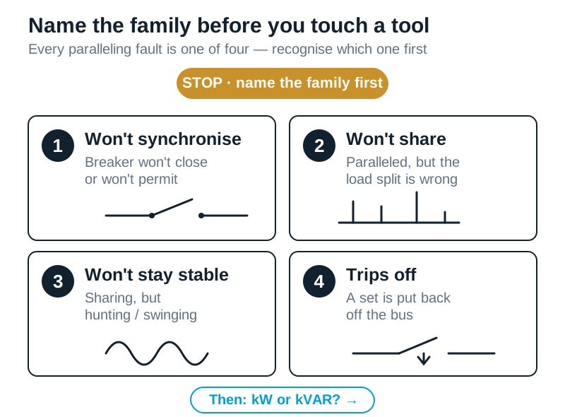
Name the family first. That is the whole discipline in one line: name the family before you touch a tool. It tells you which half of the system to look at and which checks come next, and it stops you testing the alternator when the fault is in the engine, or re-tuning an AVR when the fault is a breaker.
Hold onto those four families. Near the end they collapse into a single table you can run down at the board while the plant is tripping — but only once you understand the checks behind it, so we build those first.
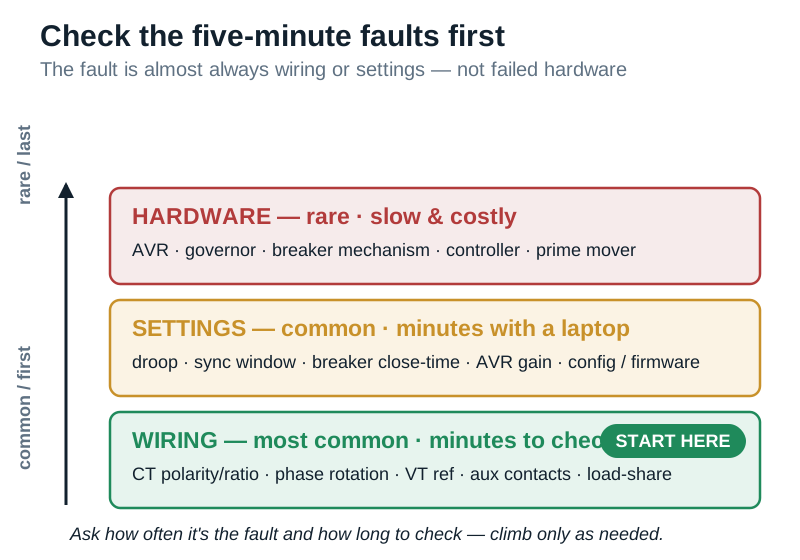
Then check the likely before the rare. This is the other half of the method, and it saves more time than any instrument. Faults are not equally probable. On a freshly built paralleling scheme, the overwhelming majority of problems are wiring and settings, not failed hardware — a current transformer wired backwards, a droop figure left at default, a phase rotation nobody proved, a breaker closing time nobody measured, a load-share link not landed, a parameter changed and not written down. Blown AVRs, failed governors and dead controllers happen, but they are rare by comparison, and they are the last thing to suspect on a new install, not the first.
Call it the Five-Minute Fault rule: prove the cheap, common, five-minute things before you condemn a component or order a spare. Ask of any suspected cause, "how often is this actually the fault, and how long does it take to check?" The cheap checks come first every time. The engineer who reaches for a replacement controller first usually finishes last — as the reversed-CT story later shows, three days can go into the expensive suspects while the fault sits on a terminal nobody opened.
The one move that halves every paralleling fault: kW or kVAR?
Once you know the family, make the single most valuable move in paralleling diagnosis: decide whether the problem lives in the real-power loop or the reactive-power loop. Almost every sharing, stability and trip problem is one or the other, and the two are fixed in completely different places.
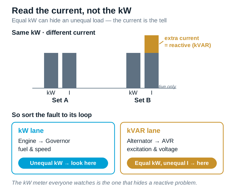
Keep it in plain terms. Real power — kW — is set by the engine and its governor: fuel and speed. Reactive power — kVAR — is set by the alternator and its AVR: excitation and voltage. Two independent control loops, and they fail independently. You can have perfect kW sharing and badly split kVAR at the same instant. Confuse the two and you will chase the fault forever. (If the two-loop split is new to you, it is explained fully in Generator Synchronization Explained — here we only use it to sort the fault.)
The tell that unlocks most of it is this: current follows kVA, not kW. The kW meter everyone watches is exactly the number that hides a reactive problem — so read the current instead. The current doesn't lie. If the kW meters read equal but one set draws noticeably more current than the other, the extra current is reactive: you have a kVAR problem, and you look at the AVRs, the excitation, and the current transformers that feed them. If instead the kW itself is split unevenly — one set genuinely carrying more real load — you have a kW problem, and you look at the governors, the speed settings, and the droop.
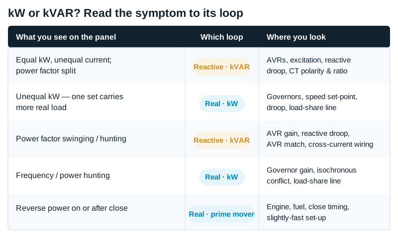
Read the symptom, name the loop, then pick up a tool. On our two-set board the first reading told the story: equal kW, one set drawing far more current. Reactive — an AVR or a CT, not a governor. That decision saved half a day at the wrong cubicle.
Family 1 — it won't synchronise, or the breaker won't close
A close can fail in two different ways. Either the controller will not permit the close, or the breaker will not physically close when told to — or, worst of all, it closes but badly. Work through them in order of likelihood.
The permissive keeps blocking. The sync-check function — device 25 — is doing its job: it will not let the breaker close unless voltage, frequency and angle are all inside a window. If it keeps blocking, the usual causes, commonest first, are a slip set too high (the incoming set's frequency is drifting past the bus too fast, so the angle races through the window before the close can catch it), a window left at the factory default and never tuned to this plant, or a genuine mismatch the synchroniser is right to reject. Check the slip and the window before you suspect the relay itself.
The breaker will not close at all. Now you are in the close circuit, not the synchroniser. Look, in order: a standing lockout or trip that has not been reset; the dead-bus interlock logic holding the breaker back because it thinks the bus is live (or dead) when it is not; the breaker not racked fully into service position; a spring not charged; the closing coil supply missing; or a wiring error in the close string. These are humble, physical faults — far more common than a failed controller.
Auxiliary contacts and breaker feedback. This one hides in plain sight. The controller does not see the breaker — it sees the breaker's auxiliary contacts (52a and 52b) telling it "I am open" or "I am closed." If those contacts are wired wrong, adjusted wrong, dirty, or chattering, the controller acts on a lie. A 52a/52b swapped or mislanded makes a controller refuse to synchronise (it thinks the breaker is already closed), or issue a close and then immediately see "still open" and fault. Intermittent aux contacts produce the maddening fault that comes and goes with no pattern. Keep the principle: when the logic and the breaker disagree, believe the breaker — the controller is only ever as honest as the contact feeding it.
Field investigation — a set that synchronised fine on Monday, refused all Wednesday, then worked again Thursday. The controller was already flagged for replacement — everyone was sure the module was dying.
Modules do not take Wednesdays off. An intermittent fault with no electrical pattern is almost always mechanical. We put a meter on the breaker's 52b auxiliary and watched it flicker every time someone leaned on the panel door. A loose aux-contact wire, not the controller — a cheap crimp, and the "faulty" module ran for years afterwards.
It closes, but roughly — and sometimes trips. This is the dangerous one, because the permissive was happy. The cause is almost always breaker closing time that was never measured or never entered. The synchroniser issues the close early, so that after the breaker has travelled, the contacts meet at zero angle. If nobody measured the real closing time and put it in the controller, the breaker arrives late, the contacts meet off-angle, and you get a rough close — a jolt, sometimes a reverse-power or overcurrent trip on the first attempt. Which is worth turning into a rule you will never forget on a slow breaker: a happy permissive is not proof of a good close. The breaker's own travel time is part of the sum. Measure it; enter it. (Why an off-angle close is violent rather than merely untidy is the physics covered in Generator Synchronization Explained — we will not repeat it here.)
Field investigation — a scheme that "grunted" every close — a thump you felt in the floor — and occasionally tripped on the first attempt. The sync-check relay was blamed and replaced. The grunt stayed.
The relay was permitting correctly; the breaker was arriving late. Nobody had measured its closing time, so the controller was compensating for a number that did not match reality, and the contacts met a few degrees off zero every time. We timed the breaker, entered the real figure, and the grunt was gone. The relay had been telling the truth all along — it just could not see the breaker's mechanics.
Phase sequence — proven once, or assumed. If two phases are reversed somewhere in the wiring, the incoming set can never come into step, and a good synchroniser will simply never permit. On a first energisation this is a real risk, and the fix is not in a menu — it is to prove phase rotation physically before the first close, every time. Assume it and you can, in the worst case, close onto what is effectively a bolted fault.
The reference the synchroniser is reading. The sync module compares voltages across the breaker through voltage transformers. A blown VT fuse, a wrong phase landed on the module, or a reference taken from the wrong side makes the synchroniser compare the wrong things — and no amount of adjustment will help until the reference is right. Cheap to check, easy to miss.
Configuration and firmware — the invisible change. Modern gensets synchronise through intelligent controllers (DSE, ComAp, DEIF and similar). Their behaviour lives in a parameter file, not on the drawing. A wrong breaker close-time entered, a sync window set too tight, the wrong operating mode selected, or a parameter changed during a site visit and never recorded will stop a close as surely as a wiring fault — and leave no physical trace. A controller firmware update that resets or reinterprets a parameter can break a scheme that worked yesterday. If the hardware is sound and the wiring proves out, compare the live configuration against the commissioned one. On our board, the first failure to close was exactly this pair: slip left too high, and a sync window still at its default — both settings, both fixed with a laptop.
Family 2 — they're paralleled, but they won't share the load
The sets are on the bus together; the load split is wrong. This is the family that puts most engineers on site. Make the kW-or-kVAR move immediately — it decides everything that follows.
The kW branch — one set hogs, the other loafs
If the real load is split unevenly, you are in the governor loop. Causes, commonest first:
- Mismatched governor droop. The classic. Two "identical" sets, but one droop figure was left different — even slightly — and the flatter set quietly takes more load. It is a single number in a menu, invisible on the drawing, and it will happily unbalance a bus that is perfect in every other respect.
- One set in droop, one in isochronous, with no load-share line. They fight for control of frequency instead of sharing. Either give them a proper load-share line, or put both on the same philosophy with one as the reference.
- The load-share line itself. Many schemes share kW through an analogue load-share line or a controller-to-controller link. If that line is not landed, broken, mis-wired, or picking up noise, the sets cannot coordinate and one runs away with the load. On modern controllers this is often a communications link (a CAN bus or a dedicated load-share network) rather than a wire — and a comms link that is unterminated, wrongly addressed, or dropping packets fails in exactly the same way, just less visibly. Check that the link is healthy and that both controllers agree they are on the same bus.
- Speed / kW set-point trim. A base-load or set-point trim left in from testing can hold one set high or low — worth ruling out early.
Field investigation — one machine took nearly two-thirds of the kW and would not let go. The obvious read was a tired actuator on the loafing set, and a replacement was already on order.
Before fitting it, we read both droop settings side by side: one on 3 percent, the other on 5. Someone had corrected one set during testing and never matched the other. Two digits changed to agree, and the load split evenly. The actuator went back in its box; a hardware swap would have fixed nothing.
The kVAR branch — equal kW, unequal current
This is the single most common real paralleling failure. The kW meters look fine; the currents do not match; the reactive load is piling onto one machine — you are in the AVR loop. Causes, commonest first:
- Reversed CT polarity — the number-one cause. A current transformer for load-sharing or cross-current compensation wired the wrong way round tells the AVR the exact opposite of the truth about reactive load, so it drives excitation the wrong way and the reactive load lands on one set. It is a one-terminal error, it is nowhere on the single-line, and it is the first thing to check when kW is equal and current is not.
- Wrong CT ratio. Subtler and nastier than reversed polarity, because it does not fully break the scheme — it scales it wrong. A CT of the wrong ratio (a 1000/5 where the design wanted 1500/5, or a replacement fitted after a fault with the ratio nobody checked) makes one set's controller mis-measure current, so sharing is proportionally off and the error grows with load. Confirm the ratio on the nameplate against the design, not only the polarity.
- A drifting or failed AVR. Excitation set or drifting high on one set pushes reactive load onto it. Less common than the wiring faults, but real — and this is where a genuine component failure does live.
- Mismatched reactive (quadrature) droop, or AVRs that were never meant to work together. Reactive sharing needs the AVRs coordinated — either matched reactive droop or a properly wired cross-current (quadrature) scheme. Mixed AVR makes or models often will not co-operate at all, and a poor connection in the quadrature circuit lets reactive current circulate between the machines with no proper correction. If the sets are not on matched, correctly wired AVRs, no amount of tuning will make them share cleanly.
Field investigation — the board from our opening. Equal kW, one set drawing far more current, creeping towards a reverse-power trip. The master move had already sorted it — reactive, not real — so we went to the CTs before the machines.
Set B's load-share CT was landed backwards. One terminal. We corrected it, proved the sharing under real reactive load, and the currents came together. A second symptom cleared with it: that same reversed CT had been feeding the reverse-power element a wrong signal, pushing a healthy set towards a trip it never deserved. One backwards CT, two faults, both gone.
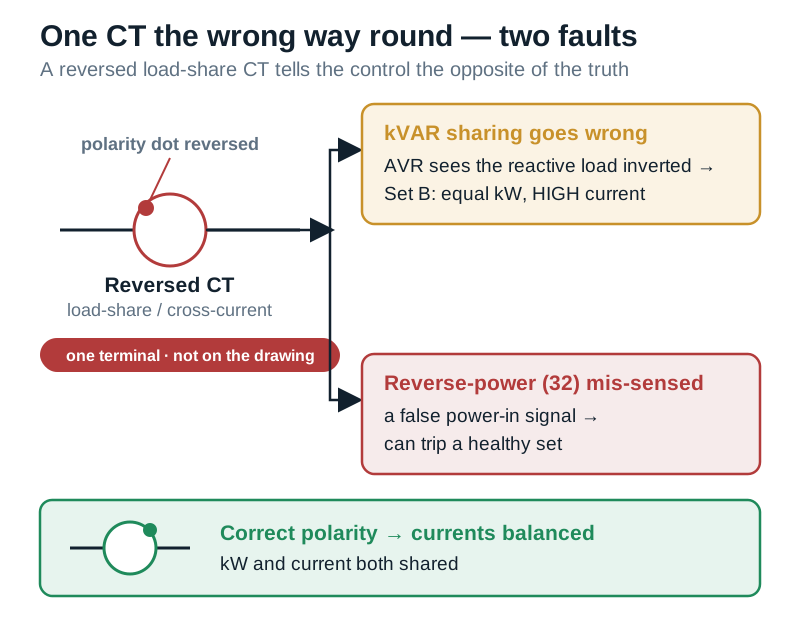
What we see on site — a bus that shares perfectly on the commissioning day's light load and falls apart the moment a real reactive load — a big chiller, a bank of motors — arrives. Reactive sharing has to be proven under reactive load, not at no load. A scheme signed off at no load is a scheme not signed off — which is exactly why the bus that "worked at handover and failed in summer" almost always failed this one test.
Family 3 — it's sharing, but it won't stay stable
Hunting is not mis-sharing; it is oscillation. The average split may be right, but power, power factor or frequency swings back and forth, sometimes badly enough to trip. Sort it by loop as usual.
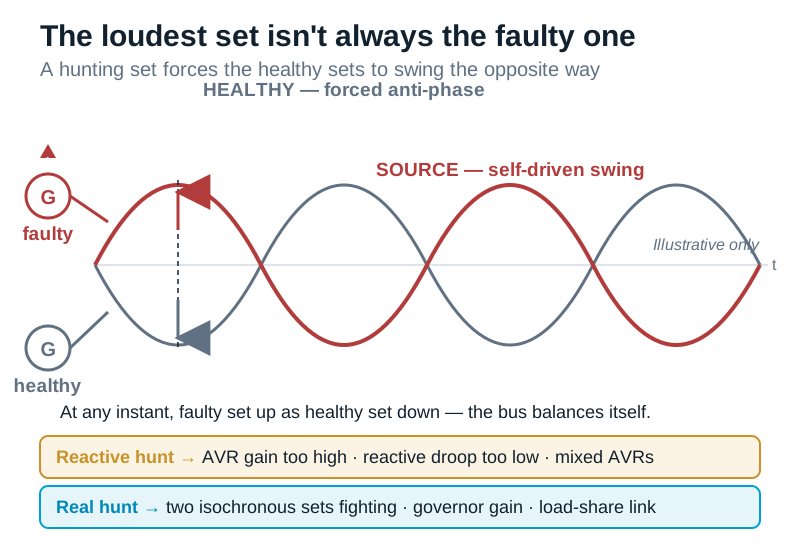
Power factor hunting — the reactive loop. The AVRs are fighting for the reactive load. Causes: reactive droop set too low, AVR gain set too high, incompatible cross-current settings, or mixed AVR types. The bus periodically dumps and picks up reactive load, and the healthy sets are forced to swing the opposite way to compensate.
Which saves a lot of wasted effort. When one set hunts, the others are forced to hunt anti-phase to balance it — so the set that looks like it is misbehaving is not always the faulty one. Chase the loudest symptom and you tune an innocent machine all afternoon. Find the source, fix it at the reactive droop and gain, and confirm the AVRs are compatible.
Frequency or power hunting — the real loop. Here it is the governors. Two isochronous sets both trying to hold frequency will fight unless one is the reference or a load-share line coordinates them; governor gain set too high oscillates; a noisy or marginal load-share link makes both controllers chase a moving signal. Give one set the reference, or add proper droop, and calm the gain.
Hunting only when a big load switches. Sometimes the bus is stable until a large motor starts or a non-linear UPS load steps, and then it rings. That usually means the settings were marginal all along and the load step exposed them. Stabilise the settings — the droop, the gain, the AVR coordination — rather than blaming the load. (Deep control-loop tuning is its own subject; the Droop vs Isochronous companion goes further than we will here.)
Field investigation — a bus that hunted its power factor no matter how patiently the AVR gains were tuned. Two engineers had spent most of a day nudging settings and watching it swing back.
The AVRs were two different makes — not one model set slightly apart, but genuinely different regulators, put on "equivalent" sets by a substitution years apart. They were never going to co-operate on reactive sharing; the fix was matching the AVRs, not the settings. You cannot tune your way out of incompatible hardware.
And check the link. On controller-based schemes, a flaky load-share communications link produces textbook hunting — the controllers coordinate through data, and if that data stutters, the loops chase it. A comms link is now as much a cause of instability as a droop setting, and easy to miss because everything looks wired.
Family 4 — it trips off the bus
A set was on the bus and the protection put it back off. The first question is not "which relay" — it is "was the trip right?" Sometimes the protection caught a genuine fault and did exactly its job; sometimes a mis-set or mis-wired relay nuisance-tripped a healthy set. Both need finding.
Reverse power (device 32) just after closing. The incoming set was closed too slow, or not brought up slightly-fast, so at the instant of closing it was being dragged by the bus as a motor instead of pushing into load. Device 32 saw power flowing in and tripped it. The fix is in the close: bring the set up as slightly-fast, and compensate the breaker closing time (Family 1) — a real trip doing its job on a bad close.
Reverse power in service. A set that was carrying load starts drawing power in. This is the prime mover losing drive — a fuel problem, an air-starved engine, a governor fault, an unstable fuel controller — while the machine is still paralleled, so the bus motors it.
State it plainly, because it is the most misdiagnosed trip in the business: reverse power is not an alternator fault. It is the engine losing power while still connected. So make it a rule — never blame the alternator first. The call-out goes to the engine and the fuel, not the generator end.
Field investigation — a set that tripped on reverse power every few days. Because the trip said "power," the callout went to the generator supplier; the alternator was inspected and came back clean.
Reverse power means the engine has stopped pushing while still connected — the machine is being motored, and the alternator is the victim, not the culprit. We found a fuel rack sticking intermittently, starving the engine for a few seconds and letting the bus drag it. Weeks had gone to the wrong specialist at the wrong end of the machine — because a protection label pointed at electricity when the fault was mechanical.
Overload or overcurrent on one set while kW looks shared. This is a kVAR imbalance cascading into a trip. The kW meters say the load is shared, but the reactive load has piled onto one machine and its breaker trips on overcurrent. The fault is not the breaker — it is the sharing (go back to Family 2). Fix the reactive sharing and the "overload" disappears.
Loss of field (device 40). An alternator losing excitation — an AVR or excitation failure. Here, at last, is a genuine hardware fault. Check the excitation system.
Trips during the match (81, 27, 59). Under/over-frequency or under/over-voltage tripping while synchronising usually means the speed or voltage was unstable during the match, or a load step hit at the wrong moment. Stabilise the match rather than widening the protection to hide it.
Relay logic and wiring — the nuisance-trip source. Before you accept any trip as real, remember the protection is only as good as its logic and its wiring. A relay set but never injection-tested is a document, not a proven function. Mis-set pickups or times nuisance-trip healthy sets; a CT feeding a protection element with the wrong polarity or ratio makes the element see a fault that is not there; trip logic wired to the wrong breaker or the wrong input trips the wrong set; and, again, chattering auxiliary contacts can drop a set off the bus for no reason the meters can explain. When a trip makes no engineering sense, suspect the relay's inputs and logic before you suspect the machine.
Why it passed on paper: the faults a drawing can't show
Step back from the individual families and notice what every root cause we found has in common. The reversed CT, the wrong CT ratio, the one droop digit, the unmeasured breaker closing time, the AVRs that would not co-operate, the mislanded auxiliary contact, the sync window left at default, the parameter changed and not recorded — not one of them appears on the single-line diagram or the protection schedule.
That is why the scheme passed on paper and failed on site. Call it the Invisible Fault Principle: the faults that stop a paralleling scheme are almost never on the drawing. The drawing shows the design; the fault lives in the wiring, the settings and the mechanics underneath it.
It is worth naming the whole class, because once you see it you stop trusting the drawing as proof:
- CT polarity and CT ratio — decide reactive sharing and what the protection sees; a terminal and a nameplate, not a drawing.
- Breaker real closing time — a measured number nobody measured.
- Droop and gain settings — digits in a controller menu.
- AVR make and model compatibility — two "equivalent" AVRs that fight.
- Controller configuration and firmware — the parameter file, and what a firmware update did to it.
- The load-share link — a wire or a comms bus, healthy or not.
- Permissive, interlock and close-circuit logic — drawn as a box, alive in the wiring.
- Auxiliary contacts (52a/52b) — the breaker's word to the controller, right or wrong.
- Phase sequence — proven once, or assumed.
- The human commissioning record — what was actually set, versus what the drawing intended, versus what someone changed on a site visit and did not write down.
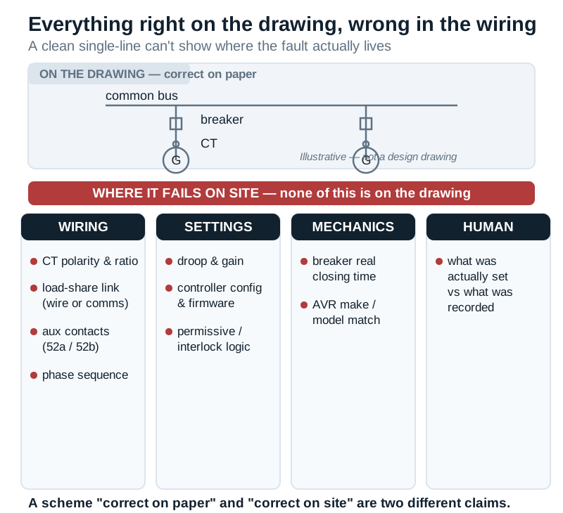
why-generator-synchronisation-fails-06-invisible-fault-mobile.svg if your theme uses it.)That last one is the root of the roots. "Correct on paper" and "correct on site" are two different claims, and only commissioning — proving each function on real load, and recording what was set — closes the gap between them. Most paralleling faults are not design errors or component failures; they are the difference between the drawing and the wiring, and between what someone set and what someone wrote down.
The same method works for utility synchronisation too
Everything above assumes the sets are paralleling with each other on an island bus. It is fair to ask whether any of it changes when a set parallels with the utility instead. The reassuring answer for a troubleshooter: the diagnostic method does not change. You still name the family, still split kW from kVAR, still check the likely wiring-and-settings faults before rare hardware, still measure the breaker and prove the CTs. A set that will not synchronise to the grid, or shares reactive load badly against it, or hunts, or trips, is failing for the same families of reason — the check-sync, the excitation, the CTs, the governor, the close timing.
What is different with the utility is not the fault-finding — it is the added protection and the permission. Utility paralleling brings interconnection protection, loss-of-mains detection, and, in the UAE, the approval of the network operator — Etihad Water & Electricity in the Northern Emirates including Ajman, or DEWA in Dubai. Those requirements, and their settings, are a design-and-approval subject in their own right, and they belong to the Paralleling with the Utility (UAE) companion, not here. So take the useful half: the method you use on a gen-to-gen bus is the same one you use on a gen-to-utility one — the extra utility layer adds protection to check, not a new way of thinking.
Which failure is yours?
Here, as promised, is the whole method on one page. At a misbehaving bus — awkward hour, building on the sets, people waiting — you do not want to re-read a guide; you want to route the symptom to its family and its first three checks and get moving.
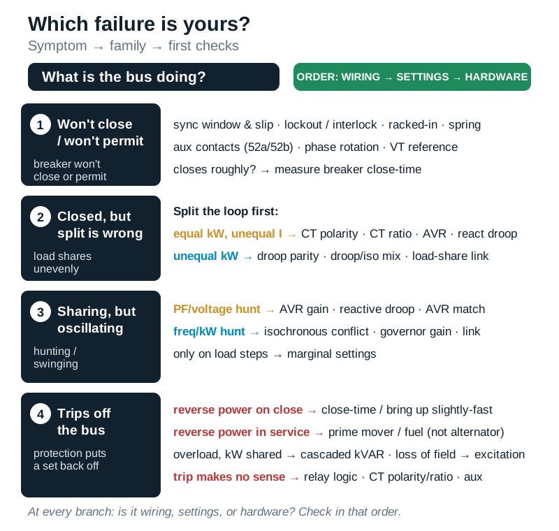
why-generator-synchronisation-fails-07-decision-tree-mobile.svg if your theme uses it.)And at every branch, the same reflex: is the fault in the wiring (CT, phase, VT, aux contacts, load-share link), the settings (droop, window, close-time, gain, config), or the hardware (AVR, governor, breaker, prime mover)? Check them in that order, because that is the order of probability.
The discipline that prevents all of this
Every fault in this guide is one a proper commissioning would have caught before handover. The number on the drawing is only the intention; the scheme is proven — or not — on site. A correct bring-up proves each of these, in order, and records it:
- Phase rotation proven physically before any first close.
- Breaker closing time measured, and entered into the controller.
- Sync-check tested to permit and to block — not assumed from a setting.
- CT polarity and ratio verified on every load-share and protection CT.
- Load sharing proven on real load — kW and kVAR both — not at no load, and not on the commissioning-day light load alone.
- Protection injection-tested against the scheme — every element proven to operate, on the right input, at the right value — not signed off from a settings sheet.
- The as-commissioned configuration recorded, so the next engineer inherits what was actually set, not what the drawing hoped for.
Do that, and the bus does on the worst night what it did on the commissioning day. Skip it, and the faults in this guide are the ones you meet later — under load, in the dark, with the building on the sets.
A few questions we're asked often
Why won't my two identical generators share load? Because sharing is two separate jobs — kW by the governors, kVAR by the AVRs — and identical hardware still won't share if a CT is reversed or the wrong ratio, the governor droop settings differ, or the AVRs are fighting. The machines are rarely the fault.
Why do the kW meters read equal but one set draws more current? Because current follows kVA, not kW. Equal kW with unequal current means the reactive load (kVAR) is not shared — a CT or AVR problem, not an engine problem.
What's the number-one cause of unequal reactive sharing? A load-share or cross-current CT wired the wrong way round. It is a one-terminal error that appears nowhere on the drawing, and it should be your first check when kW is equal and current is not.
Why does my paralleling bus hunt or swing power factor? The AVRs are fighting for reactive load — reactive droop too low, AVR gain too high, incompatible or mixed AVRs — or, on the real-power side, two isochronous governors fighting for frequency. Remember the healthy sets swing anti-phase to compensate, so the loudest symptom is not always the source.
What causes a reverse-power trip when paralleling — is it the alternator? No. Reverse power is the prime mover losing drive while still connected, so the bus motors the set — look at the engine and fuel. On a close, it means the set was brought up too slow. A reversed load-share CT can also trip the element falsely.
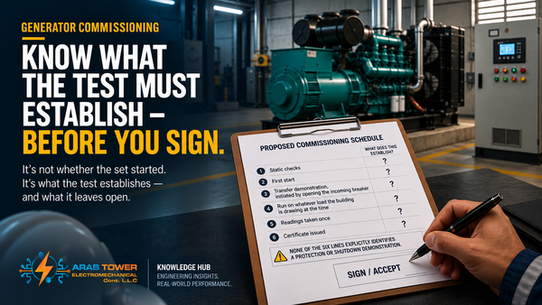
My scheme passed the factory test — why did it fail on site? Because the factory test proves the build, not the paralleling. The faults that stop paralleling — CT polarity and ratio, breaker close-time, droop settings, AVR coordination, phase rotation, the load-share link — are all site conditions, none of them visible on the drawing. A passed factory test is not a paralleled bus.
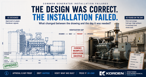
Can a correctly designed paralleling scheme still fail? Yes — and most that fail were designed correctly. The failure is almost always the gap between the drawing and the wiring, or between what was set and what was recorded. That gap is closed by commissioning, not by design.
Standards behind the diagnosis, and how Arab Tower can help
The functions and behaviours in this guide sit on established standards: ISO 8528-1 and ISO 8528-5 for generating-set ratings and load acceptance in parallel duty; IEC 60034-1 for the alternator; the ANSI/IEEE C37.2 device numbers used throughout (25 sync-check, 32 reverse power, 40 loss of field, 46, 27/59, 81); IEEE C37.102 for generator protection application; NETA practice for proving a protection setting by injection rather than assuming it; and NFPA 110 where the plant is a critical-facility standby scheme. Each sets a limit or a method — none of them finds the fault for you. That is still the engineer's job.
One last thing worth saying plainly. A paralleling scheme is only as good as its weakest connection — a CT the wrong way round, a droop setting that does not match, a breaker whose closing time nobody measured, a parameter someone changed and did not record. Each is invisible on the drawing and obvious under load. That is exactly why a second look is worth having.
So if a paralleling scheme will not close, will not share, hunts, or keeps tripping — send us the single-line diagram, the protection schedule, the controller and load-share configuration, and, if it is live, the event log. We will find out why, or commission it, and tell you what we found and why it happened. The investigation stands on its own — the same method you have just read — whether or not you bought the switchgear from us. Arab Tower has been designing, supplying, installing, testing and commissioning paralleling switchgear and synchronising controls across the UAE and internationally since 2003, and our testing and commissioning team handles the CT polarity, load-share verification, relay injection and protection side of these schemes end to end.
Talk to our engineers → · or see our LV switchgear & paralleling boards.
Continue in this series: Generator Synchronization Explained · ATS vs Synchronization Panel · Droop vs Isochronous Load Sharing · Generator Protection & Settings · Paralleling with the Utility (UAE) · Generator Commissioning (coming soon).