Sizing Generators for Hard Loads: Motors, VFDs, UPS & Fire Pumps
A tower's essential load schedule added up to about 495 kVA. The standby set that got installed was 1000. Nobody padded the schedule. Here's where the rest came from — and how to see it coming.

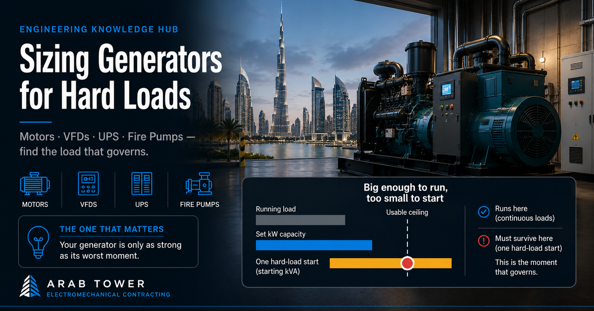
The set that was big enough — and still failed
Take a G+12 commercial tower whose standby set backs the life-safety loads, the essential services, and — the client's call — some cooling and the IT room. Add those essential loads up, apply diversity, and you land on a running demand of about 420 kW — roughly 495 kVA. Comfortable. Then the set gets specified at 1000 kVA. No load was added in between.
So where did the other 500 kVA come from?
You've seen the site version: a generator well above the running load, until the fire pump cuts in or a big motor starts across the line — the board dips, contactors chatter, a screen in the server room reboots. Nothing on the calculation sheet is wrong; the running load really is smaller than the set.
The catch is that running kW answers the wrong question. It tells you the set can carry the building. It says nothing about the worst moment — and a few loads on that bus don't ask "can you carry me?" They ask "can you take me the instant I'm at my worst?"
Which is the whole idea, in one line:
A generator isn't sized for its loads. It's sized to survive their worst moments.
Read the number that way and the gap stops being a mistake. It becomes a question: which load opened it?
Four loads on that bus are capable of it — a large motor, a rack of VFDs, a UPS, a fire pump. This article puts each one in the chair.
Four hard loads, one winner
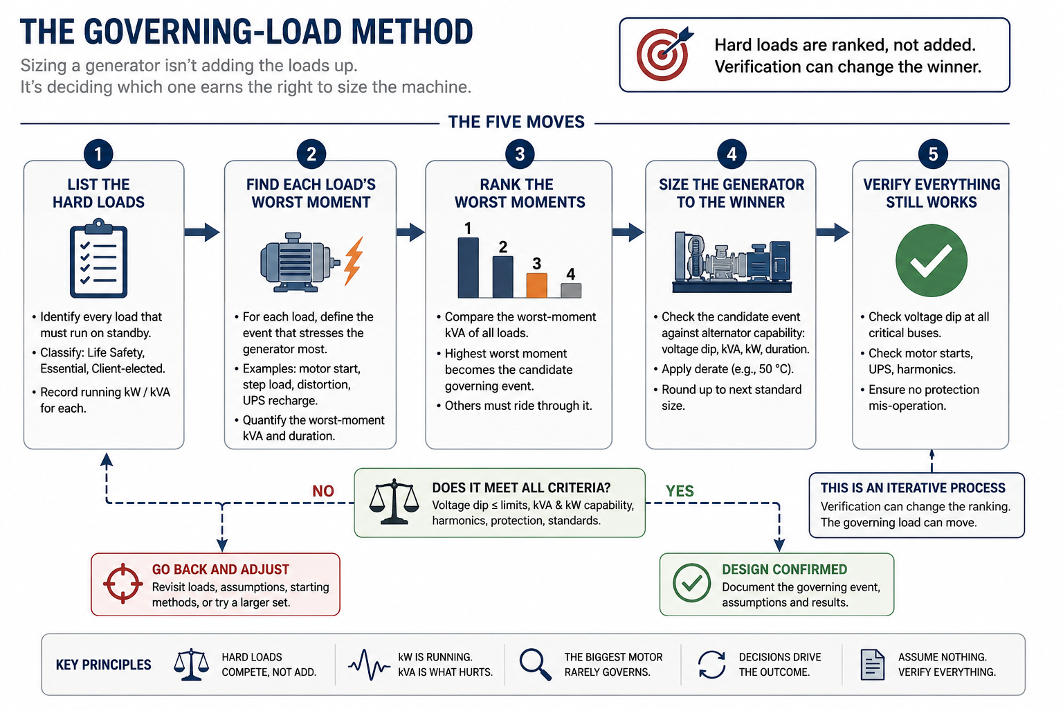
Here's the trap that opens that gap in the first place: engineers add hard loads up. Don't. They don't stack — they compete. Only one of them lands the worst moment on the set, and that one sets the size. The other three just have to ride through it.
So the skill this article is really teaching isn't arithmetic:
Sizing a generator isn't adding the loads up. It's deciding which one earns the right to size the machine.
That decision runs on five moves, every time:
- List the loads and mark which are hard.
- Name how each one hurts — starting kVA and dip (motor), continuous distortion (VFD), transfer and recharge (UPS), or the code start rule (fire pump).
- Rank the worst moment — which single event most collapses the voltage, most distorts it, or is most tied down by code.
- Size for that, with the 50 °C de-rating stacked on, because a nameplate is a lab number.
- Verify the rest ride through it. A sensitive load that resets on the dip the motor is allowed to cause is a sizing failure, not a motor problem — and it sends you back to step 3.
One thing to carry through the rest of this:
The load that wins is usually not the biggest kW on the schedule.
Will it survive the start?
Size for the motor's starting kVA, not its running kW — and the starting method is the cheapest lever you have.
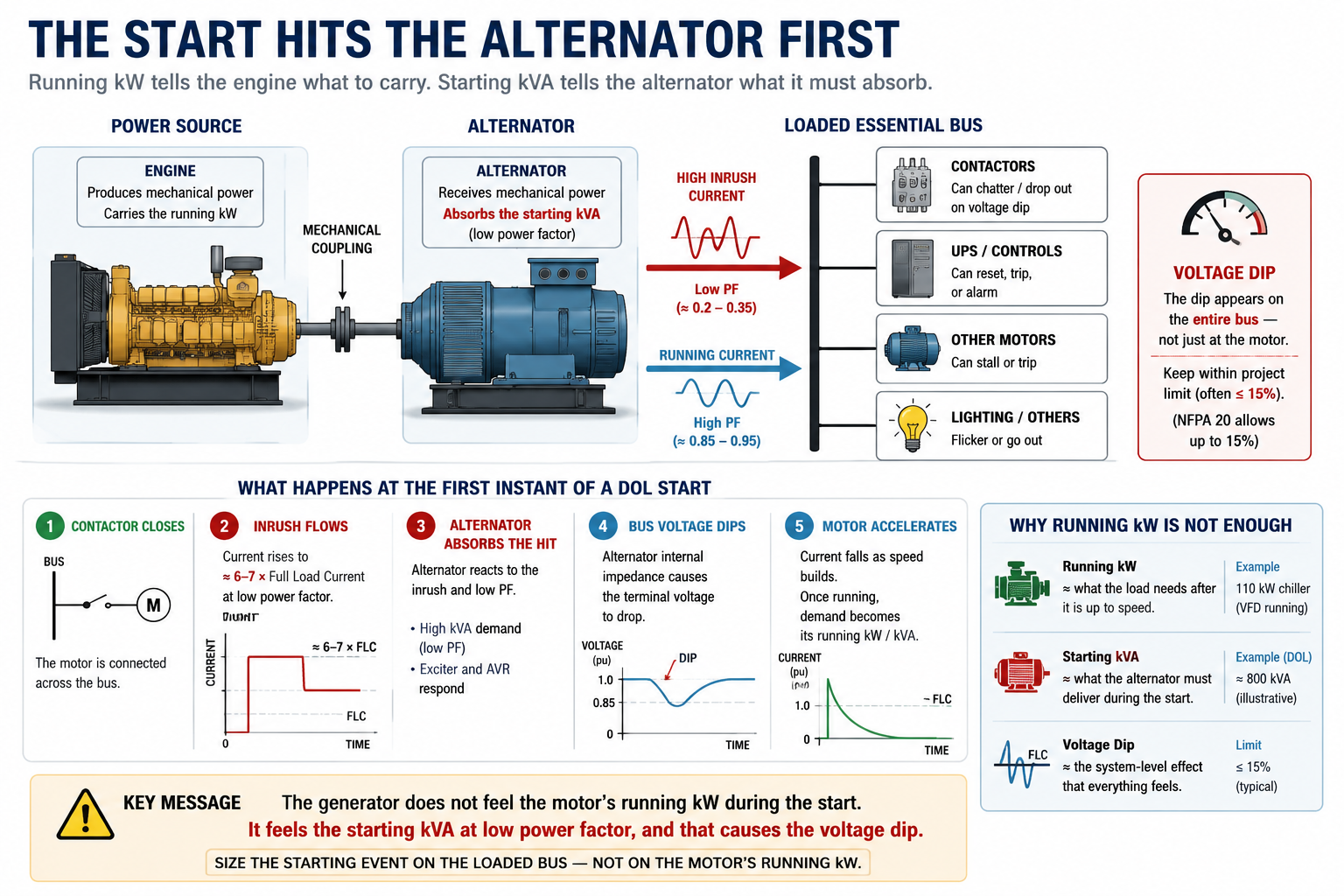
A start punishes the alternator, not the engine. For a few seconds a direct-on-line (DOL) motor pulls six to seven times its full-load current at a power factor of only 0.2–0.35 — a large starting kVA for almost no useful kW. The engine barely notices; the alternator holds the voltage, or it doesn't.
Hold the dip inside the limit — usually 15%, tighter on a bus with sensitive kit — and the start is clean. Miss it and the voltage sags far enough to chatter contactors two panels away.
How hard that moment lands is a choice:
| Starting method | Start current (× FLC) | Effect on the set | Reach for it when |
|---|---|---|---|
| DOL | 6–7× | Harshest — biggest dip | small motors, strong source |
| Star-delta | ~⅓ of DOL | About a third of the demand | legacy, mid-size motors |
| Soft starter | 2–3× | Gentle ramp, much smaller dip | large motors on a genset |
| VFD | ≈ running | Barely a step | when speed control is wanted anyway |
So — is the chiller the load that sizes the set? It's the obvious suspect: a 110 kW rooftop chiller is the biggest motor in the building, and started across the line it would throw a transient near 800 kVA — enough to size the whole set on its own. But a motor this size is rarely started that way: the disturbance is hard on the supply, and utilities and consultants usually require reduced-voltage, soft or VFD starting above a threshold. In this tower the chiller runs on a VFD, so its start is a gentle ramp — the biggest kW on the schedule barely steps the set. One reading for the ranking; hold the verdict.
Now the part that surprises people.
Soften a start and you shrink the generator more than a bigger alternator frame ever would. It's why large motors are so often put on a VFD or soft starter: it can drop the set by a whole size band, saving capital and years of fuel wasted idling an oversized machine. The starting method is a sizing decision hiding inside an equipment choice — and it's why a softened start often doesn't end up governing.
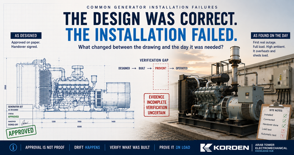
On site, a set can "pass" a start test unloaded, then dip hard the first time a big motor starts across the line with everything else on — checked in isolation, never against the loaded bus. Five years on, a set that fights an untamed start every day wears itself, and its switchgear, faster than the nameplate suggested.
On the drawing: is the starting method specified, and is the biggest start assessed with the essential load already running? At commissioning: watch dip depth and recovery, frequency recovery, and whether anything else drops out when that motor turns.
Will it survive continuous distortion?
A rack of drives can size the set harder than a big motor — because it hurts the generator every second it runs, not only at start.
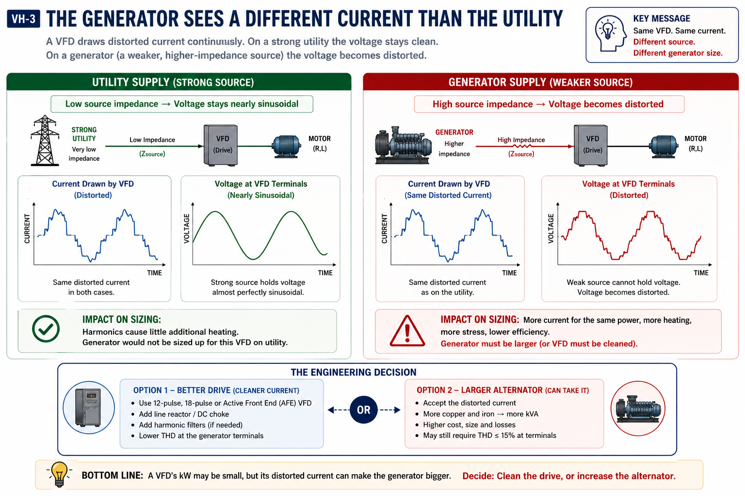
A VFD doesn't wait for a start to punish the set. It draws current in a distorted shape, continuously, and the alternator has to supply it while keeping its own voltage clean. That's harder on a generator than on the utility: the set is a weaker, higher-impedance source, so the same current bends its voltage further out of shape.
The number to hold is total harmonic distortion (THD) at the terminals — inside a sane limit (around 15%, or the stricter project or IEEE 519 figure) and the bus stays calm.
You have two levers, and this is a real choice: oversize the alternator so its lower impedance absorbs the distortion, or clean up the drive at the source. The drive's front end is where the distortion is born:
| Front end | Typical current distortion | On a genset | Reach for it when |
|---|---|---|---|
| 6-pulse | ~30% | Worst | cheapest first cost |
| 12-pulse | ~10% | Better | common step down |
| 18-pulse | ~5% | Clean | larger drives |
| Active Front End | <5% | Cleanest | premium, tight limits |
| + line reactor / filter | knocks 6-pulse down | cheap partial fix | retrofit any drive |
That old "1.5 times the motor HP" habit hides all of this. And here's the surprise worth sitting with:
In a drive-heavy building, harmonics can out-size any motor start. In a data centre or an all-VFD tower, the VFDs' distortion — not a start — is what sizes the set. The machine gets sized by the quiet, continuous distortion of loads nobody flagged as hard.
On site, the problem shows up after energising — overheating neutrals, nuisance trips, kit misbehaving — on a bus everyone signed off as sized right. It was sized for kW, not for the shape of the current. That bill arrives months after handover, as a maintenance headache the facility team inherits.
On the drawing: what front end does each major drive use, and was the harmonic check done at the generator's source impedance, not the utility's? At commissioning: measured voltage THD under load, AVR stability with the drives running, and neutral and alternator temperatures.
Will it survive the transfer?
Use the UPS maker's own generator data — and only if you remembered the battery recharge that lands right after transfer.
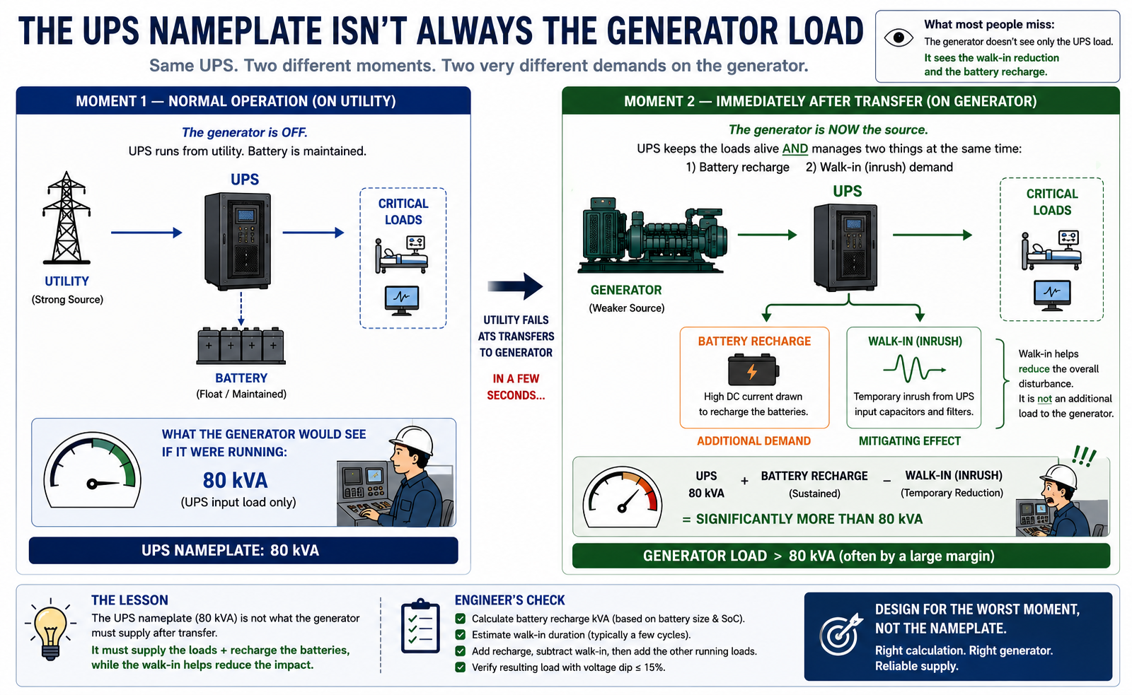
The UPS is the load that punishes a good engineer's memory. The old "1.5 times the UPS kW" rule is dead: modern units with input filters, PFC front ends or transformerless designs present a different load. The honest number comes from the manufacturer's generator-compatibility table, not a multiplier.
Two behaviours decide it — and only one usually makes the load schedule:
| The moment | What it does | Why it sizes the set |
|---|---|---|
| Walk-in | ramps the UPS onto the set gradually | helps — but only if it's actually set to |
| Recharge step | recharges the batteries just after transfer | drops an extra load on the set as it's still steadying |
Our server room runs an 80 kVA UPS. The old rule would call for ~120 kVA and stop there. The real answer takes the maker's ratio, adds the walk-in, and includes that recharge step — which, on a hot-day de-rated set, lands with less headroom than the nameplate promises.
And the surprise that catches experienced engineers:
Adding a UPS can push the generator up more than adding another motor would. A motor is a one-second event you can soften; the transfer-plus-recharge is a compound demand that arrives when the set is least ready. People miss it because only the UPS's steady input made it onto the schedule — in a data centre or a heavily-backed-up building, that recharge step can be the load that sizes the set.
For the facility team, it's worth knowing this number isn't fixed after handover: a technician can change the walk-in time or the recharge rate during maintenance — and quietly change what the generator has to do.
On the drawing: is the OEM compatibility data attached, and is the recharge step in the calculation? At commissioning: the set's response as the UPS walks in and again when recharge begins.
Will it survive emergency mode?
The code (NFPA 20) writes the rule — and the catch is a controller mode that quietly breaks the sizing you did.
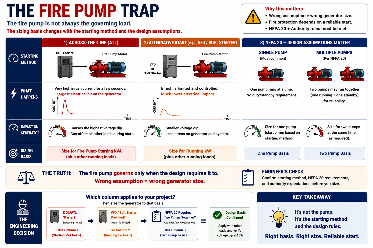
The fire pump is the one hard load where a code, not your judgement, sets the rule. Under NFPA 20 the power source must carry the locked-rotor current of the fire-pump motor plus the jockey and associated loads. The generator itself only has to be sized for the pump's full-load current — unless the controller has a mode that starts the pump across the line, in which case you size for the DOL locked-rotor case. The feeder must be dedicated and independent, and NFPA 20 allows up to a 15% dip on starting.
Here's the trap, and it springs at commissioning: an emergency or mechanical controller mode that forces an across-the-line start. You size on a soft-start or full-load assumption; then, in emergency mode, the controller starts the pump straight across the line at locked-rotor. The set dips out or trips during the acceptance test, and your assumption is gone.
Which is what puts the fire pump in contention here:
In this tower the big rotating loads are VFD- or soft-started, so their starts are gentle — but the fire pump's need not be. And not because a fire pump is always hard: it's this controller. Its emergency mechanical mode starts the 90 kW pump across the line at locked-rotor, and NFPA 20 makes us size the source for that current whatever the normal starter does. That start throws a transient near 660 kVA onto the already-loaded bus — a big number, but how it ranks against the UPS step and the harmonic limit is the next section's job, not this one's.
On site, the acceptance test is often run only in the "normal" mode; the across-the-line emergency mode never meets the generator until it's needed. And the day it's needed is the annual Civil-Defence test — the one that exposes an undersized set in front of the authority, years after everyone signed off.
On the drawing: does the controller have any mode that starts across the line, and is the set sized for locked-rotor if so? Is the feeder genuinely dedicated? At commissioning: run the fire-pump start in every mode, including emergency, with the bus loaded.
So which one wins?
The interrogation's over. Put the four on our one building and referee the fight:
| Hard load | Its worst moment | Size of that moment, in this design |
|---|---|---|
| 110 kW chiller (VFD) | ramped start | a small step — no real transient |
| VFD loads (pumps, AHUs, lifts) | continuous distortion | THD, held within limit by the alternator |
| 80 kVA UPS | transfer + recharge | a moderate step just after changeover |
| 90 kW fire pump (across-the-line, emergency) | locked-rotor start | ~660 kVA onto the loaded bus |
Line them up and the ranking makes itself. Against a small VFD ramp, a held THD figure and a moderate UPS step, the fire pump's across-the-line emergency start is the one large transient — so in this design it governs, not because it's the biggest motor, but because it's the biggest moment. The alternator has to swallow its ~660 kVA locked-rotor step while already carrying the ~495 kVA essential load and holding the dip inside 15%. Work that on a 50 °C rooftop — where the nameplate loses roughly a tenth — and the requirement lands near 900 kVA of capability at site. The next standard standby frame is 1000 kVA / 800 kW. A lower-reactance alternator might reach the 900 kVA frame; a tighter dip limit pushes it to 1100. The number is a result, not a target.
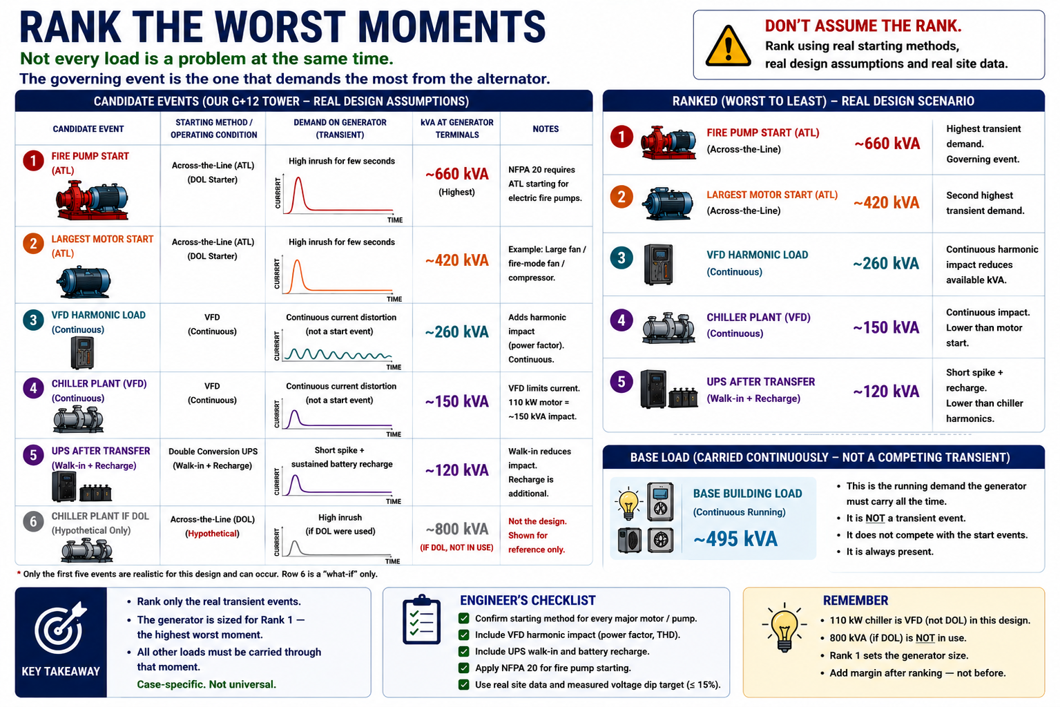
There's where the size came from. Nothing was padded; one worst moment was priced in.
Then the step everyone skips — check the rest ride through that event: does the chiller's VFD hold through the dip the fire-pump start causes, does the UPS walk-in and recharge come through, does the VFD distortion stay inside its THD limit while the set is stressed? Only when all pass is the number real.
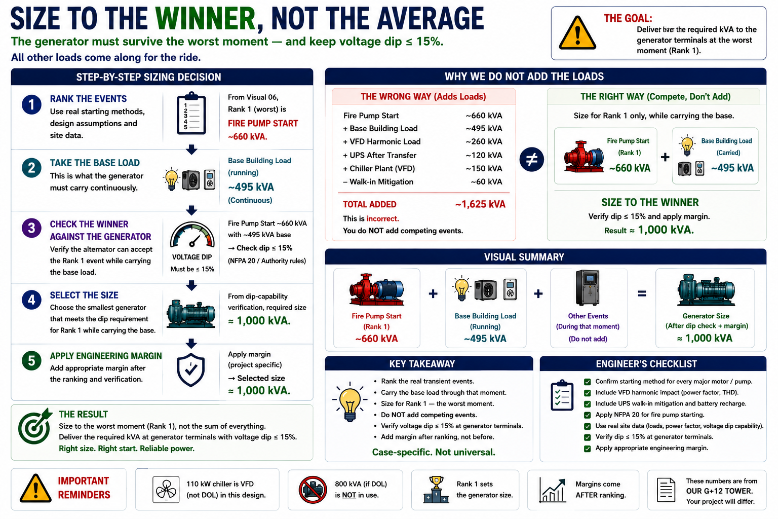
Now watch the number move with the decisions. Take the essential chillers off the standby set — a life-safety-only philosophy some clients choose — and the running base falls to ~200 kVA; but the fire-pump start still has to be ridden through, so the set is now sized almost entirely by that one start, near 800 kVA. Or specify the fire pump with a starting arrangement the authority accepts as the source-sizing basis, cutting that start by two-thirds — and the fire pump stops governing: the UPS recharge step, or the combined fan start, becomes the worst moment, and the number moves again. Same building, different decisions, different set.
Which is the real lesson hiding in the mystery:
The number was never in the load schedule. It was in the decisions.
It passed the factory. Why did it fail on site?
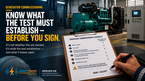
A factory test proves the wrong things for hard loads — a clean machine, kind air, no loaded bus behind the start.
The proof that matters is a load-bank and step-load test on site, with the essential bus loaded: dip depth and recovery, frequency recovery, AVR response, motor acceleration, controller alarms, every fire-pump start mode, and confirmation nothing else drops out. Measured, not assumed.
On the authority side, the UAE distribution authorities — DEWA, SEWA, Etihad Water & Electricity and ADDC — and Civil Defence (for the fire pump) set the changeover, paralleling and dip rules the scheme must obey; confirm the stance with the authority for your emirate before you finalise.
And at handover, the facility manager should insist on one thing above all: the load-bank and step-test records, plus the as-commissioned settings. That paperwork is what proves the set will still behave in year twenty, not only on day one.
Which fight is yours?
Our worked case is one commercial tower with one set of decisions. Change the building — or the decisions — and the governing event changes with it. The rows below are where it often hides, a place to look first, never a verdict:
| Building type | Where the governing event often hides — check, don't assume |
|---|---|
| Commercial | often a large across-the-line start (a fire pump in emergency mode, a fan bank); the biggest kW is usually VFD-started and rarely governs |
| Hospital | a segregated essential bus with tight dip limits — fire pump, large chillers and UPS all on essential; any of them can lead |
| Data centre | usually the non-linear UPS/rectifier load — distortion, not a motor start |
| Industrial | large motor starting and process step loads; high-inertia drives |
| District cooling | large pump starts, often staged — the start sequence decides the worst step |
| Fire-pump-led supply | the NFPA 20 source rule and the pump's start mode |
Don't read a verdict off this table. Find your building, list the real loads and their real start decisions, run the same five moves — and let the governing event emerge.
The hard-load sizing checklist
Keep this one — the design-review, site and commissioning sign-off on a single page.
Design review — question the submission if:
- The set is sized on the running total, with no governing start / worst moment identified.
- The motor starting method isn't specified, or the start isn't assessed on the loaded bus.
- There's no THD target, or the harmonic check used the utility's impedance, not the generator's.
- The UPS is sized by rule of thumb — no OEM data, or no battery-recharge step.
- The fire pump is sized on full-load only, with no check for an across-the-line controller mode.
- The 50 °C de-rating isn't applied to the governing case.
On site — confirm as installed:
- Starting method, reactors/filters and the dedicated fire-pump feeder match the design.
- The UPS walk-in time is set as assumed.
Commissioning — accept no set without:
- A load-bank + step test with the bus loaded, results recorded.
- The fire-pump start proven in every mode, including emergency.
- No other essential load dropping out on the governing start.
The one decision that sizes the machine
Come back to that gap between the schedule and the set. It was never a calculation error, and never really about motors, drives, a UPS or a fire pump. It was one act of judgement — refusing to add the loads up, and deciding instead which single problem, under this design's decisions, had earned the right to size the machine.
Get that one decision right and the rest is arithmetic. Get it wrong and no amount of margin saves you: too small and it fails on site as a variation; too big and it wet-stacks, wears, and burns fuel for twenty years while everyone calls it "safe."
Sizing a set with a hard load on it — a big chiller, a bank of drives, a UPS room, a fire pump? Send us your load schedule, single-line diagram and motor list, and our engineers will find the load that governs and give you the honest size — which may be smaller than the rule of thumb, or occasionally "your sizing is fine." From there Arab Tower can supply, install, test, commission and hand over the set and its switchgear, including the load-bank proof on site.
Size for the load that governs the worst moment — then make sure everything else rides through it.
Talk to our engineers → · or see our diesel generators.
Engineering references
- ISO 8528-1 / -5 — generator set ratings, load factors, and transient (step-loading) response.
- ISO 3046 — engine reference conditions and de-rating.
- IEC 60034-1 — rotating machines: rating and temperature.
- IEEE 519 — harmonic control and THD limits.
- NFPA 20 — stationary fire pumps: power source and starting.
- NFPA 110 — emergency and standby power classification.
- UAE authorities — DEWA, SEWA, Etihad Water & Electricity, ADDC installation regulations; Civil Defence for the fire-pump system. Confirm the current requirement with the relevant authority before finalising.
Go deeper: Companion guides: How to Size a Diesel Generator for a UAE Building · Generator Harmonics & Power Quality · Wet Stacking & Low-Load Operation · Load-Bank Testing · Generator Commissioning.